Saturday, December 22, 2007

Bussard Fusion Update

The New Mexican has some interesting news about the progress on Bussard Fusion Reactor.
Last August, as Bussard was losing his battle with cancer, the funds were restored with the support of Alan Roberts, EMC2's longtime Navy contract monitor. The company now has $1.8 million to pursue his work. If it is successful verifying the 2005 results, it would seek funding for a full-scale model, big enough to make net power, Nebel said. Bussard has estimated that such a demonstration model would cost about $200 million to build.

"Unless somebody can repeat and show other people that it's operating, it's really not scientifically acceptable," Hirsch said. But "if the idea works the way he thinks it could, and there's a good chance he's right, it will not take very big machine to show net energy."

The latest device, WB-7 (the WB refers to the children's toy Wiffle Ball), is currently under construction at a machine shop in San Diego and will be shipped to Santa Fe, where a small group of scientists is setting up a testing facility in an office park off Rufina Street. The device, like previous ones, was designed by engineer Mike Skillercorn.

"These are garage-scale experiments," said Nebel, pointing to the stock tank purchased at a local feed store. "We shop at interesting places," he added, mentioning both Home Depot and the Black Hole in Los Alamos.

Although Europeans are building a huge device to demonstrate the scientific and technical feasibility of fusion power, the U.S. has spent relatively little — about $300 million a year — on fusion research. Much of that has been focused on a competing idea called Tokamak, a program that Bussard and Hirsch started at the Atomic Energy Commission in the 1970s, which uses deuterium and tritium as fuel. Later both determined that the concept, which produces a lot of radioactivity, was impractical from an engineering standpoint.

With his own device, Hirsch said, Bussard was "swimming upstream as far as fusion community was concerned." Still, he was able to get about $14 million in funding from the Navy for his work.

Bussard felt enormous pressure to solve the fusion problems. In a letter to an Internet forum on his 2005 results, Bussard wrote that he believed that "the survival of our high-tech civilizations depends on getting off of fossil fuels ASAP, and — if we do not — we will descend into a growing series of 'oil wars' and energy confrontations that can lead only to a huge cataclysm. Which CAN be circumvented if only we build the clean fusion machines in our time."
That is one of the reasons I support this research. Civilization depends on it.
Nearly a year after shutting down the lab, Bussard presented his work — for the first time in more than a decade — to the International Astronautical Congress. He later discussed his results with Google, the online search engine company in a talk titled, "Should Google Go Nuclear?" that is widely available on the Internet. Before his death, he also set up a nonprofit organization to solicit donations to restart the work. Information is at www.EMC2Fusion.org.

Bussard's wife, Dolly Gray, who co-founded EMC2 with him in 1985 and served as its president and CEO, has helped assemble the small team of scientists in Santa Fe. Besides Nebel, 54, the group includes Jaeyoung Park, a 37-year-old physicist who is also on leave from LANL; Mike Wray, the physicist who ran the key 2005 tests, and Wray's brother, Kevin, who is the computer guru for the operation.

"If this works, it's going to be a big deal. It could take the entire energy market," Nebel said. "And drag the oil companies into the 21st century," Gray added.

Someday, they said, if they're right, a machine just 20 times bigger than the one sitting in the corner on Parkway Drive could run the city of Santa Fe.
Park and Nebel [pdf] are the researchers who discovered the POPS effect which was corroborated in part by computer simulations done at MIT by McGuire[pdf] and Dietrich[pdf].

I estimate we will see the results of these experiments some time between March and May of the coming year. I have my fingers crossed.

The New Mexican article has a great review of Dr. Bussard's life. You should go and read the whole thing.

Here is a tribute I wrote to Dr. Bussard. It has lots of links to the science of the Bussard reactor.
Wednesday, December 19, 2007

ITER Budget Cut

Science Magazine reports that the Federal Science budget has cut ITER funds to zero.
The bill set the budget at DOE's Office of Science at $4.055 billion--$342 million short of the requested amount--and the shortfall comes mainly out of two programs: fusion sciences and high-energy physics. Congress realized some savings by allotting nothing for U.S. participation in the international fusion reactor experiment, ITER, which is set to begin construction next year in Cadarache, France (ScienceNOW, 21 November 2006). Although appropriators expressly forbid DOE to shuffle money from other programs to satisfy its planned $149 million contribution in 2008, Marburger predicts that the prohibition will not stand. "I can't see DOE not living up to its obligations," he says. "The department will have to use its money to stay in the project, so [the language] really just amounts to another earmark."
I have heard rumors that Congress is interested in the Bussard Fusion Reactor. If it works out (Bussard Fusion Reactor Funded) ITER (a tokamak design) would be a waste. Or as Plasma Physicist Dr. Nicholas Krall said, "We spent $15 billion dollars studying tokamaks and what we learned about them is that they are no damn good."

We will know the answer in 3 to 6 months. At that point in time if Bussard IEC Fusion Reactors look like a dead end the budget for ITER can always be restored. Or the money could be put into other IEC devices. The advantage of IEC is that the budgets required for confirming experiments are small and the time frame for proof or disproof is short. Years, not decades or centuries.

Saturday, December 1, 2007

Transimpedance Amplifiers

A while back I made an off hand comment (can't remember where) about using a transimpedance amplifier to bring broader bandwidth diagnostics to the plasma community in general and IEC Fusion in particular.

Let me start with the MIT paper [pdf] by Carl C. Dietrich. Let us look at his Ion Detector on page 49 of the pdf. He has a nice picture of the probe on that page. On the following page he gets to the heart of the matter, a schematic representation of the detector circuitry. For frequency response estimation purposes the detector can be modeled as a 100K resistor in parallel with a 100 pF capacitor (which accounts for a probe capacitance of 5pF). The 3 dB roll off point is = .15/(R*C) - within 5%. which would be .15/(1E5*1E-10) = .15E5 = 15KHz. Pitiful. I think the scope impedance and frequency response is so limited because he has to use the very highest gain (where scope bandwidth is less) to see any signal at all. So we can estimate the signal at 1 mV p-p. Into 100 K ohms that means a current of 1E-8 Amps. About 10 nano Amps.

Can we do better? Yes. But we have to do a couple of things. One is to reduce the input impedance to get wider bandwidth and second we are going to have to amplify that current. Thanks to the proliferation of fiberoptic technology we have exactly the tool we need to do the job.

I like the Philips SA5211. It is low noise and high gain with a maximum output swing of a few volts with a 5 volt supply. It is also bipolar technology tending to make the input a bit more robust than JFET or MOSFET input technology.

So let us start with gain. The transimpedance gain (minimum) is about 20K ohms differential. What does that mean? A current of 1E-8 Amps will be multiplied by that resistance to give 2E-4 volts change between the two outputs. About 200 uV p-p or about 70 uV rms. That is a fair signal for spectrum analyzer and other RF work. Feed that into a transformer like the Mini-Circuits T1-6T and you have a package with good gain from 30 KHz out to 150 MHz and almost flat from 300KHz to 50 MHz. To look at lower frequency signals I'd use an ordinary instrumentation op amp from the differential output of the transimpedance amplifier. The AD8253[pdf] looks nice with a bandwidth of 3 MHz at a gain of 100 (40 dB). That gets us to 20 mV p-p at the output for signals in the audio to low RF range. Not bad. For the higher frequency signals I'd follow the transimpedance amplifier with a couple of 20 dB gain stages (at least) to get the signals up to the mid mV range. I like the Mini-Circuits MAR-8A which is rated out to 1,000 MHz (25 dB gain typ) and is not too hot in the high frequency gain department so that taming the circuit will not be too difficult. It also has gain from DC to 1,000 MHz - meaning we can use it to amplify RF in the mid kHz range without problems. Some amplifiers of the type do not like low frequencies because the slow waves can cause the circuits to either over heat or become unstable.

So now we are facing the last question. Bandwidth. The feedback resistance for the transimpedance amp is about 14K (I used 10 K - above multiplied by 2X to account for the differential output) with the gain of the input stage a factor of 70. So what is the input impedance seen by our current (ion) source? That would be 14K divided by the gain of the input stage (70) or 200 ohms. It has an input capacitance of 4 pF. Let us say the probe is another 6 pF or 10 pF total. Double that to account for a lot of slop in the installation.

Let us plug that into our frequency formula: .15/(200*2E-11) = 37 MHz. Not too shabby. We can double that without too much effort if we work to keep stray capacitance down. Which means that our SA5211 at 200 MHz bandwidth should be more than adequate for the job with the subsequent Mini-Circuits amplifiers making a very small contribution to reduced high frequency gain.

So there you have it - a very nice high frequency ion probe. With a minimum AC signal of 1E-8 Amps p-p and a maximum signal of 4E-5 Amps p-p (at the transimpedance amplifier - gains of the other amplifiers would need adjusting if the signal is near maximum).

Update: The 1E-8 Amp current limit is where the signal = the noise for a 50 MHz bandwidth. If a narrow band detector is used (1 KHz) the detection limit goes down to 1E-10 Amps p-p.

Friday, November 30, 2007

ITER Control

Emerging Technologies takes a look at ITER control and safety systems. They plan to sample at 5 MHZ for data acquisition.

Here is a nice pdf to get you started.

Sunday, November 18, 2007

Vacuum Pumping

I'd like to go a little deeper into the subject of vacuum pumping and easily attainable ultimate pressures.

Since this is a paper exercise we can pick any pumps we want. I'm going to look at 3 pump mfgrs. and pick their highest capacity turbo molecular pumps.

Adixen - Mag Lev [pdf]
Pfeiffer - Mag Lev
Varian [pdf]

There are two critical specifications for us. H2 pumping speed in liters/second and H2 compression ratio.


Turbo Molecular Pump Comparison
H2 Speed l/sH2 Compression Ratio
Adixen ATH-2300M12003.0X103
Pfeiffer HiMag 340028504X104
VarianTurbo V 3K-T23001.5X104


It looks like the Pfeiffer HiMag 3400 all the way.

Next lets look at a Roots fore pumps. I really like the Adixen RSV [pdf] series. The link has a great look at pumping capacities vs vacuum pressure and shows the limitations of roots blowers. Let us look at the RSV-1002. The largest standard pump. It has a pumping speed of 800 M3/hr with the model 2100 SD [pdf] roughing pump. That is about 225 l/s at a pressure of 3E-1 mbar (which for out Rough Order of Magnitude (ROM) purposes can be considered equal to 3E-1 torr). At 1E-2 mbar (where you can turn on your turbo pumps) it is about 100 l/sec. At 1E-3 mbar it is about 40 l/s. Ultimate pressure is 2E-4 mbar.

The Roots fore pumps basically stops pumping at 2E-4 torr. Given a turbo pump compression ratio in the neighborhood of 1E4 that gets us down to 2E-8 torr. Not enough. In addition the closer you get to the Roots ultimate pressure the lower your capacity. To get us lower we are going to need another turbo pump in series with the chamber pumps. Tom Ligon in an e-mail suggested using one pump to service all the chamber pumps. Brilliant idea. This should work fine as the volume of gas to be moved will be 1/10,000th of the amount (in liters) of the gas being pumped out of the chamber. Even with 10 or 20 chamber pumps you would still have a lot of excess capacity if you used a turbo pump with 1/100th the capacity of the total of all your chamber pumps. A pump of 600 l/s should be more than adequate. We leave the choice of that pump as an exercise for the reader.

So let us look at the chain of pumps. Say 6 or 10 reactor chamber turbo molecular pumps. A smaller turbo pump drawing from those pumps. A Roots blower next followed by a roughing pump. This all has to be properly sequenced to avoid damage to the pumps and systems. Then you have to sequence the various pressure reading devices depending on pressure. There should be enough work to keep the vacuum guy busy for at least a couple of weeks. Especially if s/he is budget constrained.

Update 21 Nov 007 0642z

I messed up pump volume calculations so let us go over them.

20 turbopumps X 3,000 l/s = 60,000 l/s. 1/100th of that is 600 l/sec.

Corrected in the text.

Friday, November 16, 2007

Data Collection

Dr. Bussard in his lab notes says that the ionization and other quick gas processes happen in 1 to 2 microseconds. Nyquist says that to be sure of capturing the highest frequency of interest you have to sample at 2X that frequency. Even so, if you sample at the zero crossings you will miss it. So much for Nyquist.

What we want is not just to measure process completions, but also look at what is happening in those processes. We might gain some insights. To do that you have to sample at least 3X the frequency of interest and much better 20X.

That says we need to sample at 20 MSPS. Front your sampler with a nice high speed fiber optic transimpedance amplifier in parallel with a DC (relatively) amplifier for low frequency fidelity and you have a very nice front end for a lot of the instrumentation we will need.

Stuff that will be sampled less frequently can of course use a much less expensive design.

With memory as cheap as it is these days I think that you decide what your maximum data collection time is at high speed and keep that amount of memory local. Then you have some kind of stupid simple protocol (say RS-485 as the physical layer) to collect the data. 5 MBPS shouldn't be too tough. With a 60% efficient protocol you should be able to collect the data from 1 high speed channel in 100 seconds. About 2 minutes. Twenty such channels in under 35 minutes. If you used 100 Base T Ethernet in a command-response type network you should get transmission time to come it at around 3 1/2 minutes. The slower RS-485 might be better if you have to collect data in an operational situation. Command-response Ethernet in relatively quieter environments (do a shot - recharge everything - hit it again).

Of course to see what the actual timings are like you have to pass around a synchronizing signal. Getting everything to start within 10% of the actual start time means passing out nice pulses on cables that differ in length from each other by no more than 20 inches. Not too tough.


Update: 31 May 008 0337z

EMC2 has pulled the lab notes and they are no longer available on the www. You may be able to get a copy from EMC2.

Gas Valve Design

As you can tell if you have been reading these recent posts I'm working on gas valve design. We are going to need good control of very low flow rates. Very low. On the order of 1E-3 to 1E-6 cc/second at STP.

A gas valve with a major orifice .200" in diameter will not give us much control. It goes from fully on to fully off (at the very low flow rates required) with a travel of .1 thousandth of an inch. What can be done to increase the travel and also increase the flow control?

Angle the sealing plate (assuming a soft seal such as an O-ring). This will give more control as the valve comes closer to full off. It will also make the control algorithms trickier as the gain goes up with increased opening. An orifice plate in the vale would be a help in limiting maximum flow (gain) and it would help increase control in the proportional range by adding a flow resistance to the valve resistance.

It also looks like we will need a multi stage regulator. 20 psia (5 psig) to 5 torr. 5 torr to 1E-3 torr. And the final control stage of 1E-3 torr to 1E-7 torr. Individual stages for the experimental reactor should be able to vary pressures over at least a 10 to 1 range (100 to 1 is better) to account for required gas flow variations depending on operating pressure. Once we understand operation better we can optimize for actual flow requirements.

It looks like piezo electric benders are not going to work since the travel is much too small. Something on the order of 1 to 2 micro meters. What we need is something better. A voice coil motor. That can easily give +/- 30 thousandths of an inch travel. It has a drawback in that it is magnetic in nature and thus can't be placed inside the the magnetically shielded grids. For small reactors a 2 ft length tube will add about 2 mS delay to the control system. Not good. Not insurmountable.

As the reactors increase in size delay will go up linearly with size. This is bad. Volume will go up as the cube of size. This is good. More volume reduces the need for fast control.

In fact the whole gas system may need a number of reservoirs to make the control problems tractable. It is pretty much a truism in business these days that the faster the manufacturing system can respond to demand the smaller the required inventory. So it is with any control system. We will adjust our inventories accordingly.

Turbo Pump Ratings

An education is a wonderful thing. I'm getting an education. I hope to distill it into a couple of useful paragraphs.

Turbo molecular pumps (TMPs) are rated for gas flow at a certain chamber pressure. A high volume pump I am looking at is rated at 2,000 liters a second. How many ccs a second is that at STP (not Space-Time Productions - Standard Pressure and Temperature, which is 760 torr and 273.15°K) at a chamber pressure of 1E-7 torr?

2,000 l/s * 1,000 cc/l * 1E-7 torr * 1 atm/760 torr = 2.63E-4 cc/sec @ STP

Turbo pumps have a compression ratio rating. Let us look at what that means in terms of ultimate chamber pressure in terms of the worst case gas - molecular Hydrogen. The particular pump I am looking at is rated at an ultimate pressure (on the low side) of 1E-9 torr. If the pump has a compression ratio of 10,000 for hydrogen that means the outlet of the TMP must be held at a pressure of 1E-5 torr to reach a final pressure of 1E-9 torr.

We leave the design of an actual system as an exercise for the reader. Dig out them catalogs and get the slide rules slipin.

Thursday, November 15, 2007

Detectors

I have been giving some thoughts to ionization gauges lately in terms of pressure control. What if we used one without a filament to detect ions? Put it in line with a beam path but out of the way of the beam so it doesn't become an added loss mechanism and see if you get a good signal. Bursts of high energy Heliums.

There will be problems. High energy Helium ions are going to be a heating problem. Secondary ionizations will be a problem. If the bias voltage needs to be in the MV range that will be a problem.

Still, I think something useful could be worked out. Low power test reactors can probably get by with some high temperature wire. For higher powers we may need to think of something else. By then of course we ought to know a lot more and the solution will be obvious.

Wednesday, November 14, 2007

Ionization Pressure Guages

In my effort to map out a control strategy for reactor pressure control I have been studying ionization gauges. Depending on cathode emission and plate voltage they are very linear. Given their construction and plate voltage (in the 200 to 350 volt range) their response speed should be at least in the low MHz range.

The limiting factor is going to be the current amplifier (because current is proportional to gas density). At low currents - current amplifiers tend to have low bandwidths. Should that be a problem in controlling the reactor the gauge operating conditions could be optimized for the desired control range. A second gauge operated normally could be used to turn off the gauge if pressures got too far out of range. That should give us a readout bandwidth in the 100s of KHz.

With a valve bandwidth of 1,000 Hz and a reactor fill time of 1 second with a full open control valve, pressure control to within 1% ought to be easy. A little work could bring that in to .5%. Dr. B. said that his suggested pressure was 1E-7 torr because his control system was lousy. He said the real number was about 30X higher. If that is the case an increase of density with better control should allow at least a 10X increase in pressure. For D-D that means a reactivity increase of n2/2 - about 50X. If we could keep things tight enough to get the whole 30X increase in pressure it would give a gain improvement of 450. Tight pressure control is one of the critical keys to making this work.

You can get a nice first pass of ionization gauge theory and practice from this page. Click on Introduction to Bayard-Alpert Gauges. It will bring up a [pdf] "open or save" block.

Which has got me to thinking. If POPS causes density waves in the plasma and those density waves get coupled to the neutrals it may be possible to use an ionization gauge to measure POPS frequencies. You would use a diplexer. The low frequency signals would go to the pressure controller and the high frequency signals would feed the POPS frequency controller phase detector (after suitable division if required).

BTW if you are going to use CMOS I used to highly recommend the Philips 74HC4046 however Philips is no longer in the Semiconductor business. Instead that business is now called NXP. So here is NXP version of the 74HC/HCT4046A[pdf]

Thinking About Control

I keep thinking about test reactor control issues - things that need controlling, signals to use for control. I want to leave off things like cooling and other secondary functions which are quite important but are easily controlled and instrumented and happen on relatively long time scales.

Reactor controls are going to be a bitch. Let me run down the list of what needs controlling, some of the interactions and what signals we can use for feedback. This will be in relation to a test reactor about 1 meter across in total dimensions designed for continuous operation burning D-D.

1. Anode (called a grid in the Bussard Reactor) HV
2. POPS frequency, POPS voltage (added to Anode DC)
3. Gas Pressure
4. Electron Injection

Controlling the pumping speed of the turbo pumps is an option but that is rather slow and need only be done to set the base gas flow from the gas pressure controller. We could also vary the magnet current, but again that is slow and is relatively easy to do a set and forget based on the well voltage and the system geometry. So that sets out what we have for plant controls.

What kind of feedback signals can we get?

1. Neutrons - they tell us the fusion rate.
2. Light (PMT amplified) - electron density.
3. X-Ray output with energy binning - who knows what we might learn
4. High Energy Alpha Output - fusion rate
5. Pressure gauges - gas flow
6. High Frequency Current Transformer in the Anode Circuit Ground - you can learn a lot by watching

Burning D-D simplifies things. So far as we know there are no peaky resonance regions in the curve so we don't need to figure out how to keep the reactor anode voltage at some process determined level. So that is one complication out of the way. Second off we can use a high vacuum pressure gauge with out worrying about readings being gas composition dependent.

So we have pressure control. From a quick look at what is out there in terms of pressure measuring equipment it looks like ten measurements a second is a reasonable rate. That means that we probably will have a first order roll off on the loop of about 1 second. That is not too bad as the way the system works helps us. If it takes a certain time T to reach a given pressure it takes 10T to get to 10 times the pressure. Given that fact and the fact that the flow is initially designed to fill the reactor in 1 second control within a 2 to 1 range ( from .6 times the set point to 1.5 times the set point) should be easy. Tighter control of course would be better. We should try to get faster updates from the pressure measuring eqpt. Or we could opt for lower flow from the gas delivery system. Since most of the flow rate will be determined by the capacity of the turbo molecular pumps we could also go for a flow system calibrated to deliver 80% of the required flow and then just have a variable valve to make up the difference.

So gas density should be another set and forget.

That really leaves us only one thing that needs to be controlled on the fly. POPS frequency. Since we plan on impressing it on the Anode the anode current would not be a good place to read it out. If we used an antenna inside the reactor it would have the same problem. What we need is a signal read out that is independent of moving charges. The most likely signal for that is either the X-ray detector or the neutron detector. Since POPS for a drive voltage of 50 KV is expected to be in the 2 to 30 MHz range we will need a neutron measurement or X-Ray measurement system that can give us output at those frequencies. Also the detector efficiency should be such that it can detect at least .3E9 photons or neutrons a second if we are to reliably detect 30MHz. That will be tough. POPS experiments may need to be done with a sweep generator without feedback on small reactors.

Ideally if enough alphas are generated it should be possible to turn off the electron guns and just use the electrons left behind by the fusion alphas as the electron source. Of course if the electron guns must be left on they could be modulated at the POPS frequency and read out could come from the Anode ground current, considerably simplifying matters. The light output (PMT Amplified) could be used as a signal to throttle back the electron guns.

However, we really do not want continuously operating electron guns in a power reactor except for startup. They get in the way mechanically unless they can be placed on the walls of the reactor.

Tuesday, November 13, 2007

Orifice Sizing

I have been mulling over the flow control problem for a small test reactor and I think I have at least a partial solution. First lets lay out the dimensions of the problem. Let us say that the reactor is a sphere with a diameter of .9 meter and a core diameter of .3 meter. The volume of a sphere is 4/3 π r3. A fair approximation for our work is 4 r3. So the volume of the outer sphere is 4 * (.45)3 = .36 m3. Minus the inner volume of 4 * (.15)3 = .014 m3 hardly worth worying about. So we won't. So we are at about .35E6 cm3 for volume.

Now how about pressure. We want to keep the pressure in that volume below 1E-7 torr. What is that in atmospheres? To help us along we have a handy pressure calculator. The answer is 1.3E-10 atmosphere. Times .35E6 cc. So it takes about 5E-5 cc at STP to fill the chamber.

Now it turns out that there is a dandy orifice company called Lenox Laser who appear to have just what we need. An orifice calculator. Let us set it up to fill our tank in one second. That should give us pressure control of better than 1% if we can get our valve to go from on to off in a millisecond. So we start with an inlet pressure of 1 torr to our control valve. The other side of the orifice will be at chamber pressure. 1E-7 torr. Since we are figuring this for Deuterium we will use He4 as a substitute for 2H2 (a Deuterium molecule). Use 273.15 Kelvin for the gas temperature. A flow rate of 5E-5 cc/sec. And we have an answer. 9.7 microns. Say 10 to make it even. A small orifice. Not the smallest (they go down to 1 micron).

From their catalog [pdf] you can scroll down to page 28 and find a nice 10 micron orifice that is drilled into a 1/4-28 set screw for under $100 bucks. Or if you get a disc from page 3 under $35.

Now of course we haven't taken into account any gas the turbo pumps are taking out or that is being burned up as the Deuteriums fuse (a minuscule amount) but at least we know what ball park we are in and at the lowest flow we are likely to want we can do the job. Now for that 1 torr regulator.

Update 1924z 19 Nov 007

We can look at some turbo pump estimates. Let us suppose we have 6 turbo pumps each capable of 3,000 l/s pumping speed. How much flow would be required? Let us look at the low end. That would be 18,000 l/sec or 1.8E6 cc/sec. If we start at 1E-7 torr that would be about .24E-3 cc/sec at STP. I have decided to have an intermediate regulator to get the gas pressure down to 1E-3 torr to the final regulator.

So what hole sizes do we need? Let us start with our original

Inlet to Outlet
1E-3 to 1E-7 torr 5.0E-5 cc/sec 40 microns

1E-3 to 1E-8 torr 2.4E-5 cc/sec   28 microns
1E-3 to 1E-7 torr 2.4E-4 cc/sec   87 microns
1E-3 to 1E-6 torr 2.4E-3 cc/sec 275 microns
1E-3 to 1E-5 torr 2.4E-2 cc/sec 870 microns

Saturday, November 10, 2007

PID Loops And Leak Valves

PID Loops (Proportional, Integral, Differential) are probably the most common kind of control loops in existence. They are easy to set up. If you do them in software they are easy to code. Plus they are fairly robust to changes in the environment. Good stuff.

This all came up as a topic of discussion during a look at what it might take to maintain a constant pressure in a Bussard Test Reactor that had coils about 1/3rd of a meter across. Here is some of the discussion from my side with some corrections and updates:

I'm not familiar with controlled leak valves. (I am more familiar than I was - Controllead Leak Valve). If they are ON/OFF type valves you may be able to get better control of low rates by using 5 or 8 valves in a 1-2-4-8- flow sequence. Kind of a gas flow D to A converter. If you then have a pressure regulator up stream to control the gross flow rates that might be all the flow control you need.

Or it may be way more than you need.

A rough estimate of your needs can be figured by calculating the allowable delta P vs delta T. (pressure vs time). Looking at the volumes involved. The gas dead space in the valve. Valve reaction time. Pumping speed. etc. to find out what ball park you have to play in.

I can help with PID loops (at least at the pseudo code level - actual coding if you use FORTH) if that would do you any good. The main thing is to reduce dead times as much as possible (esp time from valve close signal to flow <10% of open valve flow - or if it is a proportional valve to 10% of its last programmed rate. Same when going from off to on except the relevant number is 90%.). You also have to consider measurement delay including gas diffusion time. It may be that reactors below a certain size are not practical for continuous operation.

Your gas pressure measurement should be as close to the valve as reasonably possible. We can compensate for initial over measurement (i.e peak higher than final value), what is harder to compensate for is the loss of time.

BTW if you code your own loops use the form the Chemical Industry folks use where everything is in terms of overall gain and time parameters. It will simplify your tuning job. Disturbance response tuning is a nice simple way to get into the ball park. Or ask me. We can even make it auto-tune if you like.

Controller output = K ( e + Σe*Δt/Ti + Td*Δe/Δt) where K is gain, e is error from set point Ti is integration time and Td is derivative time and t is just time.

Setting the loop is simple. You input a small step in your process. The slope of the first order response determines you gain K. The dead time determines Ti. Td is 1/10th Ti. In noisy processes Td will make things worse and should be set to zero.

Of course you could do it with independent gains for each term, but that doesn't give you the reality connection thinking about overall gain and time does.

Update: The Step Response method is called the Cohen Coon Tuning Method. Here is one method for using it. None of the numbers used is etched in stone. They represent a particular type of filter operating within a particular frequency range. A more aggressive response with its attendant twitchiness may be just what you want. Or you might wish for a gentler response - easy does it.

BTW with respect to the above method I like to get my response times and amplitudes from the 20% point to the 30% point of ultimate response. Things are pretty linear in that area so no need to resort to natural logs in the calculations. Which is kind of handy if the computing must be done within a short time in a limited memory microprocessor. In any case with PID pretty close is often all that is required to be pretty good. The only time a real plant will operate exactly the same way every time is when it is generated from a formula. In fact the integrator is required because plant resistance to change varies - with time, operating point, settings on other plant controls, wind, rain, sunshine and sun spot cycles. Gain gets you close. Integration zeros out the residual error. Differential prevents you from coming in to the final value too hot. It also helps when the error is getting bigger.

Here is a plant simulator that is some fun to play with.

Wiki is pretty good on PID. When you get down to the bottom they do a good job of relating theoretical PID loop mathematics to useful PID loop mathematics. As far as I know the motor control guys still like the theoretical math and the chemical plant guys like the practical math. I'm a motor guy, but my vote on the subject is with the Chemical Plant control guys.

Friday, November 9, 2007

Research Speed

One way to keep things moving along at a good clip is to do things in parallel. When it is done on a computer chip it is called pipelining.

So here is one way to pipeline the research.

Every test reactor station has one set of power supplies. It should have 3 reactors so that:

1. One is operational for testing.
2. One is being modified.
3. One is cooking out preparatory to testing.

Testing then can go on almost continuously.

Since the power supplies are the major cost driver for a test set up designed for continuous operation, and because the supplies will not change much with time, sharing the supplies with three nearly identical reactors should give a significant time advantage without much added cost. In fact cost per hour of use will decline with more intensive use since you are paying for less idle time.

Wednesday, November 7, 2007

Burning Pu And Other Stuff

It is mentioned quite frequently that burning up excess Plutonium is the best way to restrict its availability. A few days ago I was discussing the use of a Bussard reactor as a proliferation device. I looked at why it need not be a net power producer to be a useful high flux neutron source. I looked at it from the point of turning abundant U238 into scarce (in some places) Pu239. Bomb material.

Now let us look at it from another point of view. A way to safely burn up Pu239.

Reactors with a lot of Pu in them are hard to control for technical reasons having to do with delayed neutrons. There are 1/3rd as many as with U235, which is bad for Pu.

However, with a Bussard neutron generator (as opposed to a Bussard Power Generator which would produce 1/1,000th as many neutrons for a given fusion power output) you could design a reactor that was inherently safe (can not go critical because of the geometry) that could burn up the Plutonium and provide power out. To make the reactor stop you just hit the power switch. To throttle it up or down just control the voltages on the neutron generator (the Bussard neutron generator) at the center of the reactor.

With the possibility of explosions because of fuel loading and geometry (actually steam explosions caused by power pulses) in current reactors because they have to be loaded with several years of fuel to be economical and they have to produce their own neutrons, a complete rethinking of the whole business is in order. With a proper neutron source enriched uranium might not even be needed for nuclear power.

If the Bussard Neutron Generator (burning Deuterium) produced any thing like break even (fusion energy out = electrical power in) its use at the core of a fission plant could be very workable if the fission energy gain was sufficient. With a maximum theoretical gain of 100 or so (neutron energy in + other losses vs fission energy out) this should be very workable.

I want to be very clear here to differentiate between the two types of Bussard Reactors. One would be designed to fuse Deuterium. That reaction produces a lot of neutrons. The other type of Bussard reactor burns an isotope of Boron - Boron 11 and Hydrogen (when stripped of its electron it is referred to as a proton). What I like to call the pBj reaction. proton Boron joules. Which means smash the proton into the Boron and you get energy out.

One of the things we can do to reduce out of the box proliferation is to design the p-B11 reactors to have a lower tolerance for radiation so that if they did get diverted they wouldn't last long. Then you mostly have to keep an eye on the D-D jobs with fusion outputs above 100 Kw or so. Plus the clandestine folks.

Monday, November 5, 2007

WB6 Lab Notes Added

To the Fusion Resources area of the sidebar.

Thanks to John P. at Talk Polywell.

A Suppliers List has been added to the Sidebar.
Superconductors
Vacuum Vessel Components - insulators, feedthroughs, HV and LN2 connections.


Update: 31 May 008 0337z

EMC2 has pulled the lab notes and they are no longer available on the www. You may be able to get a copy from EMC2.

Sunday, November 4, 2007

We Had Better Get A Move On

There is a very interesting discussion of the nuclear proliferation aspects of the Bussard Fusion Reactor going on at Talk.Polywell. Here is what I think needs to be done:

We need to build Bussard Reactor neutron generators as soon as possible to test out possible proliferation aspects - like trying to make Plutonium - so we can figure out the best ways to control the proliferation problem.

The cat is out of the bag. We better start looking for a leash.

The idea was suggested to me by my friend Eric of Classical Values.

Other Instrumentation - Mass Spectrometer

It might be useful to have a Mass Spectrometer Optimized for Atomic masses in the range of 1 to 4 AMU, 1 to 12 AMU and 1 to 25 AMU, or other ranges as might seem handy.

==

Make your own Mass Spectrometer from off the shelf parts:

R. M. Jordan Co.

Holding Back Fusion

The Government Accountability Office (GAO) has just released a report on the state of nuclear fusion in America. It is not good. Here is an excerpt from the executive summary.
GAO has identified several challenges DOE faces in managing alternative fusion research activities. First, NNSA and the Office of Fusion Energy Sciences (OFES), which manage the inertial fusion program within DOE, have not effectively coordinated their research activities to develop inertial fusion as an energy source. For example, they do not have a coordinated research plan that identifies key scientific and technological issues that must be addressed to advance inertial fusion energy and how their research activities would meet those goals.

Second, DOE may find it difficult to manage competing funding priorities to advance both ITER-related research and alternative magnetic fusion approaches. DOE officials told GAO they are focusing limited resources on ITER-related research activities. As a result, as funding for ITER-related research has increased, the share of funding for the most innovative alternative magnetic fusion research activities decreased from 19 percent of the fusion research budget in fiscal year 2002 to 13 percent in fiscal year 2007. According to DOE officials, this level of funding is sufficient to meet research objectives. However, university scientists involved in fusion research told us that this decrease in funding has led to a decline in research opportunities for innovative concepts, which could lead to a simpler, less costly, or faster path to fusion energy, and reduced opportunities to attract students to the fusion sciences and train them to fulfill future workforce needs. Finally, while the demand for scientists and engineers to run experiments at ITER and inertial fusion facilities is growing, OFES does not have a human capital strategy to address expected future workforce shortages. These shortages are likely to grow as a large part of the fusion workforce retires over the next 10 years.
Inertial fusion is all about using laser pulses to create enough pressure to cause a pellet of fuel frozen to near absolute zero to implode with enough pressure to fuse the frozen elements. So far there is no plan to turn this into a power producer. Brilliant management. Just brilliant.

In addition they have no plan to meet their manpower requirements by training scientists and engineers. They should try reading The Mythical Man Monthby Brooks. They are setting themselves up for a regenerative failure.

Another inertial approach is the beam or IEC approach. Standing for Inertial Electrostatic Confinement. This uses electrostatic fields to focus and accelerate the beams with various methods used to reduce beam collisions with the accelerator electrodes. The Bussard Fusion Reactor is one example of such a device which uses magnetic fields to reduce losses. There are others.

Then we have the problem of ITER sucking up funds like a runaway Hoover. Choking off other promising approaches. Like alternative magnetic fusion approaches such as the Spheromak. Between all the magnetic approaches such as ITER, other tokamaks, other magnetic confinement approaches, and laser implosion, the budget for various IEC approaches is tiny indeed.

Here is an excerpt from the full report.
The ITER Organization faces several management challenges that may limit its ability to build ITER on time and on budget and may affect U.S. costs. Many of these challenges stem from the difficulty of coordinating the efforts of six countries and the European Union that are designing and building components for ITER and, as members of the ITER Organization, must reach consensus before making critical management decisions. The key management challenges include (1) developing quality assurance standards to test the reliability and integrity of the components made in different countries; (2) assembling, with a high level of precision, components and parts built in different countries; (3) finding a new vendor if a country fails to build a component on time or does not meet quality assurance standards; (4) developing a contingency fund that adequately addresses cost overruns and schedule delays; and (5) developing procedures that describe which countries will be responsible for paying for cost overruns.
I smell a boondoggle. The Euros had this problem with the Airbus A380 Fiasco. So you can't say they don't have enough experience to screw things up. They have had practice.

Here is more about the laser inertial confinement program.
DOE has three separately funded inertial fusion research programs: NNSA’s inertial fusion research activities related to the nuclear weapons program, a High Average Power Laser Program (HAPL) to develop technology needed for energy for which funding is directed by a congressional conference committee, and OFES’s inertial fusion research activities aimed at exploring the basic science for energy applications. Experiments in each of these programs help advance inertial fusion energy, but these experiments are not coordinated and each program has a separate mission and different scientific and technological objectives.
Evidently the European management model is popular in the USA too. Who knew?

I'm not sure exactly what program is being referred to here. It looks like IEC which is distributed among a number of labs and university locations.
As another alternative to both the laser systems and the Z-machine, OFES is funding experiments using heavy ion beams to produce fusion energy at the Lawrence Berkeley National Laboratory. Heavy ion beams are made by a particle accelerator—a device that uses electrical fields to propel electrically charged particles at high speeds. The heavy ions, which are heavier than carbon atoms, collide with the targets and cause the compression and heat needed to release fusion energy.

However, in fiscal year 2006, OFES spent about $21 million to fund 25 small-scale experiments at 11 universities, 4 national laboratories, and 2 private companies to test 7 types of magnetic fusion devices with different shapes and magnetic currents. This level of funding represents a decline over the past 6 fiscal years—from $26 million in fiscal year 2002 to $20 million in fiscal year 2007. University scientists involved in innovative fusion research told us that this decrease in funding was not consistent with a 1999 DOE fusion energy science advisory committee study that recommended OFES increase funding for innovative magnetic research activities. OFES relies on this advisory committee to establish priorities for the fusion program and to provide a basis for the allocation of funding.

However, since that report, the share of funding for innovative research activities has decreased even as funding for fusion research has increased. The share of funding has dropped from 19 percent of the fusion research budget in fiscal year 2002 to 13 percent in fiscal year 2007. In addition, while OFES’s 5-year budget plan shows an increase in funding for fusion research activities in fiscal years 2008 through 2011, most of this funding will be used for ITER- and tokamak-related research activities at the major facilities. DOE officials also told us there are planned increases in funding for innovative devices, but only to maintain the same level of research. According to university scientists, a number of innovative approaches are ready to advance to the next stage of development that would test the feasibility of producing fusion energy or conduct more sophisticated experiments, but DOE has no plans to advance any of these approaches because it may require an increase in funding to conduct more sophisticated experiments. DOE’s fusion energy advisory committee has not assessed the appropriate level of funding between ITER- and tokamak-related activities and innovative concepts since 1999, before the U.S. joined ITER and it became a priority.
So they are choking small money fusion research to pay for ITER. This is nuts when any one of the small approaches migh deliver a breakthrough that could reduce the time and money to develop actual fusion power.

So you get the idea. Typical big governmentitis. The ideas with the most political clout win. Ideas with small experiments, few researchers and low cost results get squeezed out because they lack a constituency.

Pretty much what Dr. Bussard said in the audio found here and the video found here.

If you think it is time for a change, contact your government.

House of Representatives
The Senate
The President

Give them an earful. The future will soon be upon us and we need to be ready.

Tuesday, October 30, 2007

Lab Tools

I'm making a list of lab tools. Random jottings for now. If some Mechanical Engineers have suggestions - I'm a little light in that area - chime in in the comments and I will expand the list. Plus any EEs have ideas chime in. Or any one else.

No good suggestion refused.

Electronics Lab
Production Microscope
Spectrum Analyzer
Network Analyzer DC - 1 GHz
LCR Analyzer
HV DC and AC measuring eqpt.
Radio - 10 Hz to 1 GHz AM/FM/CW
Circuit Board Prototyper - LPKF or equivalent
High Speed sampling scope
High speed analog scope
Current probes

Mechanical Lab
CNC Mill - 17" or more travel + rotary table
CNC Table Top Mill
CNC Lathe - 36" or more between centers
CNC Lathe Table Top
Surface Grinder

Computer Lab
Plotter
Logic Analyzer

Update: 05 N0v 007 1508z
Computer Lab added

Monday, October 29, 2007

It's Official

Defence News has a story up on the death of Dr. Robert Bussard in which they state that the US Navy has put up nearly $2 million to continue the research on the Bussard Reactor.
Robert Bussard, inventor of a promising method for producing energy from nuclear fusion, died Oct. 6. He was 79.

Bussard received nearly $2 million under a U.S. Navy contract in August to continue work on an inertial electrostatic confinement reactor he had developed. The reactor uses magnetic fields to confine electrons, whose negative charge causes protons and Boron 11 atoms to fuse. The fusion sets off a chain of reactions that produces electricity.
I have a bit to say about Dr. Bussard's life work at Dr. Bussard has died.

You can find out more about the Bussard reactor at the following urls.

Bussard Fusion Reactor
Easy Low Cost No Radiation Fusion
Bussard Reactor Funded
Dr. Bussard's Final Interview
IEC Fusion Newsgroup
IEC Fusion Technology blog

Sunday, October 21, 2007

Donations Requested

To keep this place running I could use some support of the financial variety. The ISP wants to get paid. The hard drive is running low on space. etc.

If you would like to help visit: Support Requested.

Monday, October 15, 2007

Dr. Bussard's Final Interview

Tim Ventura has a 53 minute audio interview of Fusion Pioneer Dr. Robert Bussard at his site American Anti-Gravity. Let me give you a bit of what Tim has to say.
In our exclusive interview, Bussard describes the disenchantment with big-science Tokamak research that led him to return to the roots of Farnsworth-style fusion in the "Polywell" project that he initiated in 1986. Funded for over 20 years by the Department of the Navy, Bussard's EMC2 corporation was tasked with solving 19 fundamental challenges that stood in the way of designing commercially viable Farnsworth fusors - and in an unexpected twist, a race to bring the prototype online after project funding was cut in 2006.

Never straying far from the dream of manned spaceflight, Bussard's Polywell design is exceptional in being not only designed for high-efficiency, but also for portability - making it perfect for not only the Navy's intended use in powering ocean vessels and submarines, but also for providing high output thrust for proposed nuclear space-applications. Bussard's first intended application was an 8-foot diameter naval reactor capable of generating 100-megawatts of output energy, with the ultimate goal of using these reactors in high-velocity transorbital spacecraft capable of reaching the moon in less than 8 hours time.
To hear the audio go to Tim's site. He has links there. It is a most interesting talk and well worth your time. Dr. Bussard discusses his Fusion Reactor and other Fusion developments like Cold Fusion and Sonic Fusion. He explains why the last two, though real effects, are unlikely to lead to net power production.

Let me add that the US Navy funded Dr. Bussard's research this past August, about two months before he died. Two scientists from Los Alamos National Laboratories, one a long time friend of Dr. Bussard's, continue the work.

Cross Posted at Classical Values

Thursday, October 11, 2007

Dr. Robert W. Bussard Has Passed

Tom Ligon who worked for Dr. Bussard has informed me that Dr. Bussard has died. A sad day for all of us in the IEC Fusion community. A great one has passed. We are all diminished by his loss.

Fortunately his work will continue. A whole community has developed to support his work:

EMC2 Fusion
IEC Fusion Newsgroup
IEC Fusion Technology blog
Talk Polywell
Open Source Fusor Research Consortium II
NASA Fusion/Spaceflight Forum

Dr. Bussard was well known to Star Trek fans for inventing the Bussard Ramjet.
The Bussard ramjet method of spacecraft propulsion was proposed in 1960 by the physicist Robert W. Bussard and popularized by Carl Sagan in the television series and subsequent book Cosmos as a variant of a fusion rocket capable of fast interstellar spaceflight. It would use a large ram scoop (on the order of kilometers to many thousands of kilometers in diameter) to compress hydrogen from the interstellar medium and fuse it. This mass would then form the exhaust of a rocket to accelerate the ramjet.

In the Star Trek fictional universe vessels commonly have magnetic hydrogen collectors, referred to as Bussard collectors or Bussard ramscoops. Those are seemingly fitted on the forward end of the twin "warp nacelles", and have a "reverse" function that allows for spreading hydrogen as well as sucking it in.
Dr. Bussard is also known for his recent work on the Polywell Fusion Reactor.
The Polywell is a gridless inertial electrostatic confinement fusion concept utilizing multiple magnetic mirrors. It was designed by Robert Bussard under a Navy research contract, and is intended to overcome the losses in the Farnsworth-Hirsch fusor to create fusion power.
Dr. Bussard has left a great legacy.
In 1960, Bussard conceived of the Bussard ramjet, an interstellar space drive powered by hydrogen fusion using hydrogen collected using a magnetic field from the interstellar gas.
Some of his earliest work was in the area of nuclear fission rockets.
In 1956, Bussard designed the nuclear thermal rocket known as project Rover.
Dr. Bussard initiated some of the first major work on nuclear fusion in the United States.
In the early 1970s Dr. Bussard became Assistant Director under Director Robert Hirsch at the Controlled Thermonuclear Reaction Division of what was then known as the Atomic Energy Commission. They founded the mainline fusion program for the United States: the Tokamak. Later, in June 1995, Bussard claimed in a letter to all fusion laboratories as well as to key members of US Congress, that he, along with the other founders of the program, supported the Tokamak not out of conviction that it was the best technical approach but rather as a vehicle for generating political support, thereby allowing them to pursue "all the hopeful new things the mainline labs would not try".
If you would like to see Dr. Bussarrd in action and learn a little more about the Polywell design you can find out more at Easy Low Cost No Radiation Fusion.

My tears are flowing but the work will continue. God bless you Dr. Bussard and Warp Speed.

Update: 09 Oct '007 0244z

Rand Simberg has some thoughts.
David Bullis at Jerry Pournelle's site had a few thoughts.

I also want to thank from the bottom of my heart Eric Scheie and Justin of Classical Values who got me interested in Dr. B's work with this post and this one.

The Fusor Net folks have some thoughts.
The Talk Polywell people add their thoughts.

Update: 09 Oct '007 2043z

You can hear Dr. Bussard and Tom Ligon on The Space Show. I was honored to be able to ask a question. You can listen to the May 8th, 2007 MP3 here.

New Energy and Fuel has a couple of posts up:

Dr. Robert W. Bussard Passes Away
Details On Dr. Robert W. Bussard Passing Away

I will be adding links without further comment or update notices. Check back:

Centuri Dreams
Dad2059’s Blog of Science Fiction
Focus Fusion Society

Cross Posted at Classical Values and Power and Control

Wednesday, October 3, 2007

Two Manifolds

Here is a theory of the universe I came up with over the last few months. It may just be a crock but I'm having fun with it while awaiting the results of WB-7:

I have been working on a theory of the universe. It is probably stupid so if there are some physics guys out there who can critique this I'd appreciate it.

My theory says that the Universe consists of two manifolds at right angles to each other and that all particles in the two universes are traveling at the speed of light. Because of that relationship the Lorentz equation falls out naturally.

i.e. v12 + v22 = c2. Thus v22 = c2 - v12

with the subscript 1 standing for our universe (manifold) and subscript 2 standing for the manifold we can't "see".

I discuss how I came up with it at Talk Polywell.

The equivalence of matter and energy is intrinsic to such a formulation. What is mass in one manifold becomes energy in the connected manifold. And vice versa.

Let me add that I found this recently and it inspired me to keep thinking about the problem:

The discovery of the electron spin - S.A. Goudsmit. I'm another math challenged guy interested in Physics.

Friday, September 14, 2007

Maxwell Don't Live Here

There have been numerous people asking how it is possible that the Polywell anneals the particle energies so that plasma does not Maxwellianize (thermalize). That is the situation where through particle collisions particle energies are no longer bunched but get spread out in a thermal distribution. It turns out MIT has the answer.
Experimental fusion production and energy efficiency in IEC devices to date has been hindered by confinement limitations. Analysis of the major loss mechanisms suggests that the low pressure beam-beam interaction regime holds the most promise for improved efficiency operation. Numerical simulation of multiple grid schemes shows greatly increased confinement times over contemporary single grid designs by electrostatic focusing of the ion beams. An analytical model of this focusing is presented.

With the increased confinement, beams self-organize from a uniform condition into bunches that oscillate at the bounce frequency. The bunches from neighboring beams are then observed to synchronize with each other. Analysis of the anisotropic collisional dynamics responsible for the synchronization is presented. The importance of focusing and density on the beam dynamics are examined. Further, this synchronization appears to modify the particle distribution so as to maintain the non-maxwellian, beam-like energy profile within a bunch. The ability of synchronization to modify and counter-act the thermalization process is examined analytically at the 2-body interaction level and as a conglomeration of particles via numerical simulation.
Self bunching at a resonant frequency is a klystron type phenomenon.

It looks like Dr. Bussard got the re-normalization of energy correct but got the mechanism wrong. It may not be an edge phenomenon at all but a beam phenomenon.

Here is a nice animated picture of an electron simulation showing the bunching. Click on the icon to get it to play.

Here is more from MIT on plasma behavior in an IEC device.
Also, a curious synchronizing collective behavior is observed in simulation. Particles injected uniformly in 3 separate beam paths ‘clump’ and form pulses. As the simulation progresses, these pulses are observed to synchronize between the beam channels. The steady-state behavior under constant injection is then observed to be a global pulse with the majority of the confined ion arrived near the center of the device at the same time.
Update: 27 Sept 007 0851z

Here are a couple of good papers on the experiments:

Experimental Procedures - Dietrich [pdf]

Theory Derived From Experiment - McGuire [pdf]

Thursday, August 30, 2007

Processing Power

As you know I like FORTH a lot for control applications. I was estimating that with standard off the shelf hardware we might get a PID loop interval in the 4 KHz range.

However, there is a new kid on the block. The SEAforth 24B.

This kid is a screamer. It has 24 cores that each run at 1 G instructions per second (Ips). Peak of course is 24 G Ips.

For a PID loop that means loop cycle times in the 10 MHz to 50 MHz range. But that is not all:

* Static/dynamic memory interface
* Eleven SPI I/O ports
* Two 18-bit A/D converters
* Two 9-bit D/A converters
* 32 Parallel I/O lines

C18 Processor Features

* 18-bit stack oriented engine
* Runs VentureForth™ programming language as native code
* Executes 1 VentureForth instruction / ns
* 512 words RAM / 512 words ROM
* Hardware 18x18 multiply/accumulate
* Automatic sleep mode at <1mW dissipation

The multiplier will be very handy for PID loops. If you design your PID loops correctly they will consist of adds, subtracts, and a few multiplies.

Update 02 Sept 007 1023z

The A/D is a VCO and a counter. Which means conversion times on the order of 15 to 20 uSec. The D to A is a VCO type device as well.

What that means is that for actual high speed operation the SPI ports will probably be required.

In any case for low speed signals these ports should be fine.

Also the multiplier is actually a 9 bit by 9 bit bitwise hardware multiply. Nine or more clock cycles to complete a multiply. Some stack manipulation will be required to to do an 18 bit by 18 bit multiply. It will probably be somewhat slow. Probably 50 to 100 clock cycles. Meaning about 1E7 multiplies per second for each core. Which means that if you have one core for P one for I and one for D you could probably do a PID loop at a bit better than 5 million loops a second. If you cut down the number of bits to 12 or 14 you could tune the multiplies to make them faster.

Update 03 Aug 007 0743z

It appears the 24B is not currently being offered. The A version has the following specs:

* Twenty-four C18 core processors capable of combined sustained 24 Billion operations / second
* Completely asynchronous for faster processing and lower power
* Static/dynamic memory interface
* One SPI I/O port plus a broad set of serial and parallel ports
* Two 18-bit A/D converters
* Two 9-bit D/A converters

C18 Processor Features

* 18-bit stack oriented engine
* Runs VentureForth™ programming language as native code
* Executes 1 VentureForth instruction / ns
* 64 words RAM / 64 words ROM
* Automatic sleep mode at <1mW dissipation

A more detailed look at the chip can be found at SEAforth 24A.

Update: The SEAforth 24a pdf is no longer available by direct link. The above link now takes you to the page where you can order a copy.

Thursday, August 23, 2007

Bussard Reactor Funded?

I just received an e-mail claiming that the Navy has funded Dr. Bussard to complete his WB-7 fusion reactor experiment. In addition the e-mail claims the Navy is on board for the full up power demo if the WB-7 results are positive.

If I get further confirmation on this and permission to post it, I will. ASAP!

Update: 30 Aug 007 1436z

I can confirm the above facts. I'm not at liberty to disclose my sources. Expect a confirmation from the Navy in the coming weeks. I am just as anxious for a public announcement as you are.

Wednesday, August 8, 2007

The Inflationary Universe

Michael Turner of the University of Chicago talks about the Big Bang and the Inflationary Universe. A deep subject given a light hearted treatment. You might want to get up to speed on the physics idea of "time horizon" in relation to the speed of light before digging in. Or keep repeating the section from about 7 1/4 minutes in on the first video until it makes sense. His "view graphs" owe a lot to Batman Comics. The videos require "Real Player".

Michael Turner - video 1

Michael Turner - video 2

More Cosmology Videos

H/T Commenter Cynthia at The Reference Frame

Monday, August 6, 2007

ITER To Use ANSYS

ITER plans to use Ansys Software for various simulations.

Here is a press report.

Weld It Shut

I have been giving a lot of thought to sealing the electromagnets. It will be difficult to do a seal with fasteners that will keep the leak rate low enough.

It may be necessary to weld a cap over the seams or do some other kind of welding or perhaps silver solder if an appropriate metal is used for the coils. Electron beam or laser welding may be an option.

The coil design should be well tested before we seal them to make sure that unbuttoning them is not a regular occurrence.

Sunday, August 5, 2007

Superconducting Magnet Advances

Here is an interesting paper on recent advances in elevated temperature (20K) superconductors.
We investigated the effect of nanoscale-C doping on the critical current density Jc and irreversibility field Birr of Fe-sheathed MgB2 tapes prepared by the in-situ powder-in-tube method. The tapes were heat treated at 600-950C for 1 h. Higher values of Jc and Birr were seen for 5 at.%C-doped MgB2 tapes at higher sintering temperatures, where substantial substitution of boron for carbon occurred. The C-doped samples sintered at 950C showed the highest Birr, for example, at 4.2 K, the Birr reached 22.9 T. In particular, at 20 K, Birr for the C-doped tape achieved 9 T, which is comparable to the upper critical field of the commercial NbTi at 4.2 K. This role of nano-sized C particles can be very beneficial in the fabrication of MgB2 tapes for magnetic resonance imaging applications at 20 K.
I sure hope this stuff is available commercially by the time we decide to build WB-100. And think of it. Another good use for Boron.

Considering that we are quite happy (for now) operating at the 1T to 2T range, we might be able to go higher than 20K operation. If higher fields seem useful we can go to lower temperatures.

Thursday, August 2, 2007

Gain And Power Out

I have been mulling over for some time how Dr. Bussard came to the conclusion that power gain scales as the fourth power of the magnetic field times the radius and that power out scales as the fourth power of the magnetic field times the radius cubed.

I think I have the answer thanks to our number magician Indrek. The very first graph is I to v. The I is the coil current. The v is the velocity of the electrons. The coil current is directly proportional to the magnetic field. The energy of the electrons goes up as

1/2 m v2

Where m is the mass and v is the velocity.

That tells us that the energy of the electrons that the magnetic field can confine goes up as the square of the magnetic field. Since the density of electrons that can be confined also goes up as the square of the magnetic field and the density of the electrons determines the density of the two reactants power goes up as the fourth power of the magnetic field as does power gain since the densities are multiplied to get the power output. In addition power gain goes up for the same reason.

The second part of the power equation - r cubed - is easy to figure. The bigger the reaction volume the more power out.

So the last question is why does the gain go up as r ? Easily answered. Electrons only have a chance of escaping the reaction area if they hit a magnetic wall. At a given electron energy (it would be fixed no matter the size of the reactor) the time it takes to go from magnetic wall to magnetic wall depends on the distance the walls are apart i.e. the size of the reactor. Bigger reactors inherently have lower losses or to put it another way - higher gains.

Electron Guns

I have been looking at the electron gun question. How to design them how many amps of current they have to deliver.

Electron Gun Power

Electron Gun Suppliers [pdf]

Electron Beam Welding Primer

Joel, aka Tony Russi had this to say at NASA Spaceflight about expected electron gun currents (edited slightly for clarity):

The drive current in amperes to balance electron losses:
Ia = (Eq x Npcc x Vcc / Ts) x 1/ Gmj, where
Eq = electron charge in coulombs i.e. 1.602E-19,
Npcc = average inside electron density per cubic centimeter,
Vcc = volume of Polywell in cm3 i.e. 1.4E4, (4 π r3/3 )
Ts = electron transit time in seconds across Polywell(R=15cm),
Gmj = recirculation-corrected confinement factor.

The formula describes electron motion in a Polywell. The factor Npcc x Vcc is the total number of electrons inside the Polywell. Dividing this quanity by the time for each electron to cross from one side of the sphere to the other gives the rate at which electrons hit the confining B-field at the edge of the well i.e. the rate at which electrons try to escape. Dividing these factors by recirculaing-Gmj is the same as multiplying by the probability of escape per electron, which gives the rate at which electrons escape. Finally, multiplying all that by the charge on one electron gives the rate of charge loss in coulombs per second. An ampere(A) is, by definition, equal to one coulomb per second.

===

Joel/Tony - I think that is an excellent first cut!

A Spread Sheet to calculate electron current requirements. It is called Electron Rqmts.xlr

Wednesday, August 1, 2007

Electron Gun Power

The Electron Guns are going to require some hefty filament supplies. I was looking at the EIMAC Catalog to get some ideas on filament power. Several 1 Amp tubes I checked had filament powers on the order of 450 watts. A 7 Amp tube I looked at was over 1.5 Kw.

Sunday, July 29, 2007

Heat Transfer Book

Nice book on heat transfer (Thermodynamics lite) no charge. One of the authors is from MIT.

A Heat Transfer Text Book

H/T greenhillsofearth

Saturday, July 28, 2007

Polywell In One Easy Lesson

This assumes an understanding of the basic configuration. If that is not the case start here.

====

The electrostatic field is used to accelerate the electrons and ions.

The magnetic field traps the electrons. The trapped electrons attract ions. The ions form a virtual anode. The electrons form a virtual cathode.

The purpose of the magnetic field is unitary - reduce electron losses. It does this in two ways. Magnetically bottling the electrons. Shielding the anode from electrons.

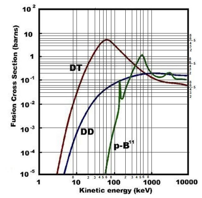
Fusion Cross Sections

Fusion Cross Sections Center of mass frame of reference. Note: the graph can not be read correctly at this scale. Click on it for a larger version.

From Fusion Formulas [pdf] via Tom Ligon

Reactor Building Sketches

Here is a sketch of WB-7x low power test reactor:
Fusion Reactor


Here is a sketch of WB-100M 100 Megawatt test reactor:
WB-100M


Click on sketch for larger version.

*

Wednesday, July 25, 2007

Fusion - False Alarm

It turns out California To Fund Bussard Fusion is a false alarm:

Here is Joe Strout's comment at Wed Jul 25, 2007 5:09 pm at Talk Polywell.
UPDATE: I got a call back from Bill Maile in the Governor's office. He spoke with the Governor's policy advisors, and in brief, the story is false. This is the first anyone in the Governor's office has even heard of the idea.

He is going to do some research to try and find out the source of the story. Hopefully he'll have better luck reaching somebody at nextenergynews than I have; the site lists no name or phone number, and is registered through domainsbyproxy.com. But maybe a Governor's office carries enough weight to shake loose some real contact information from them. We'll see... He promised to call me again within two hours, and when he does, I'll let you know what he found.
This is very disappointing. However it does raise the visibility of the effort and has gotten some exposure at the Governator's office. It is possible that this may have some good fall out. It is starting to reach political circles. Well, I loved the buzz while it lasted.

Update: 26 Sept 007 2137z

The reactor has been funded by the US Navy:

Bussard Reactor Funded

Tuesday, July 24, 2007

California To Fund Bussard Fusion

Wonderful News!!!! Governor Schwarzenegger of California is planning to fund Dr Bussards IEC Fusion project.
In a move sure to impress environmentalists and further cement his Earth friendly image, Governor Schwarzenegger is set to launch a multimillion dollar research effort into a revolutionary new source of clean non-polluting power.

The project is focused on the Inertial Electrostatic Fusion reactor invented by the award winning American physicist Dr. Robert W. Bussard. The Radiation Free Fusion Reactor has the potential to change the whole landscape of energy generation, which is usually a choice between bad and worse options that include Nuclear, Coal and Natural Gas systems.

The State of California peak energy usage is about 40,000 Megawatts and is only expected to grow steadily over the coming years . Fusion opens a whole new avenue of cheap clean energy that could not on

ly satisfy growing energy needs but also fuel massive water desalination plants that could help solve California’s acute water shortages.

Fusion is the energy that powers everything in the universe. The sun's energy comes from fusion. Alternatively, fission is the process whereby heavy atoms, which are nearly unstable, are split into two radioactive atoms. Fusion, on the other hand, is when two light atoms merge.

The fusion process invented by Dr. Bussard takes boron-11 and fuses a proton to it, producing, in its excited state, a carbon-12 atom. This excited carbon-12 atom decays to beryllium-8 and helium-4. Beryllium-8 very quickly (in 10-13 s) decays into two more helium-4 atoms. This is the only nuclear-energy releasing process in the whole world that releases fusion energy and three helium atoms -- and no neutrons. This reaction is completely radiation free.
It is not completely neutron free. However, the neutron production is minimal.

This is the break though in funding I have been looking for for the last nine months.

Better than sex.


Update: 26 Sept 007 2137z

This is a false alarm. However, there is good news. The reactor has been funded by the US Navy:

Bussard Reactor Funded

Update: 18 Oct 007 0011z

Dr. Bussard has died. The work will continue under the guidance of the US Navy.

Saturday, July 14, 2007

Fusion Symposia

Physics Essays has a symposium every two years to discuss the status and interesting papers dealing with fusion research.

Here is a description of their purpose in relation to the Seventh Symposium
The objective of this series of Symposia is to assess the benefits, applications, and spin-offs of nuclear fusion research, including both conventional and alternative approaches......

A Seventh Symposium is scheduled for 5-9 March 2007. Lawrence Livermore National Laboratory, Los Alamos National Laboratory, Naval Research Laboratory, Osaka University and Sandia National Laboratory endorse the Symposium. Invited and contributed papers will be part of the Symposium. Invited observers will also be included.
Vincent Page of GE wrote a very interesting paper on the commercialization of fusion energy for the Sixth Symposium.
  • Fusion reactors must be sized reasonably.

  • Current cost estimates for the ITER project are approximately $6 billion.

  • GE’s present quarterly earnings are “only” $4 billion.

  • We don’t want governments to build fusion reactors, we want private industry to build them.

  • Designs need to be feasible with power output in the 15 MWe to 1500 MWe range and cost < $6700 per KWe.

  • (MWe = MW electrical, KWe = KW electrical)

  • More expensive machines will not be commercially viable.

  • Competition will only occur if private industry is involved.
Page has a lot more details on the economics, but those are his main points. One other important point he makes is that the real target is coal base load plants at $1,000 capital costs per KWhe or gas turbine peakers (without a steam cycle) at about $500 KWhe.

I think his main point is correct. Other than the physics, ITER and other similar tokamak fusion reactors are a waste of money. It will not lead to viable fusion power plants even if it works, because working size is estimated to have to be in the 10s of GWe range. Even if the fuel is free capital costs are a killer. On top of that you have to figure out how you are going to get all that electricity from where it is generated to where it is used.

Dr. Robert Bussard makes the same point in his video "Should Google Go Nuclear" which you can watch here. He gets a good laugh from the audience (about 12 minutes into the video) when he says about physicists working on ITER, " they don't think it will ever work, but is really good science". His friend, Plasma Physicist Dr. Nicholas Krall said, "We spent $15 billion dollars studying tokamaks and what we learned about them is that they are no damn good."

ITER is costing the USA $400 million a year. It would seem to me that it ought to be possible to come up with $20 million in government funds to try out some of these other ideas.

One thing that gives me hope is that private venture capital is supporting Tri Alpha Energy. I expect to see more venture capital in the field over time.

Friday, July 13, 2007

Tubes

The understanding of vacuum tubes is essential for the understanding of the Bussard Fusion Reactor.

Here is a page that has links to a number of downloadable books in pdf. All out of copyright.

The Chaffee book [pdf] is a good place to start.

Friday, July 6, 2007

Power Supplies - Update #1

My thinking on the power supplies has evolved.

What I'm considering now is a 400 or 500 VDC power bus (maybe two of them) SCR regulated from a 3 phase power supply. 12 pulse for reduced filtering requirements.

The bus will supply the power for 100 V @ 25 A converters (parallelable) for the magnet supply, and 1,000 V @ 25A converters (series amenable) for the high voltage.

If each converter has its own phase trigger, the phases can be staggered so that the effective ripple frequency will be the drive freq. (around 30 KHz) times the number of converters, times 2 (for full wave rectification). For a 1,000 A @ 100 V magnet supply that puts the ripple up at about 2.4 MHz. Easy to filter. A 20 KV @ 25 A supply would have 20 converters. That would give a 1.2 MHz ripple. A full up 80 KV @ 25 A supply would have 4.8 MHz effective ripple.

Update: 08 July 007 1856z

On the HV side we will also need 24VDC (nominal) @ 25 A to power any controls on the HV side including UC2901 feedback modulators. Plus 120VAC @ 60 Hz 10 KW for misc power. The 24VDC will be battery backed to supply surge currents. There will also be quench SCRs (into resistive loads) for shorting the magnet supply and the HV supply. The resistors to be sized so that the supply output is discharged in .1 second or less to 1/10,000th of the maximum voltage or current.

Update: 09 July 007 0757z

I have been thinking about safety issues. Most notably what happens when utility power is lost? First off if the LN2 pump is pumping it should keep pumping for a few minutes after power loss. Which means battery backup. Second any water cooling must continue for a few minutes after power off. The water chiller need not be backed up. The control computer needs to be battery backed up. In fact it should operate from the battery bus at all times so power glitches do not affect its operation. The same will be true of the data collection computer. In addition a backup generator with a 48 hour gasoline supply should be provided. All important loads should have automatic transfer switches to the backup generator. Power transfer should be sequenced to minimize the surge load on the generator.

Thursday, June 28, 2007

Reactor Building and Reactor Controls

I have been thinking about a reactor building. Hexagon or octagon? I lean towards octagon. Open top cell. I'll have to look at gamma ray "sky" factor scattering to see if that is a problem. An open top would make it easier to string unanticipated wires or pipes.

I'm thinking partial shield at this time. I think that would be OK since I'm contemplating a switch gear yard to one side of the building. That would allow a truck entrance from the switch gear side. I'd rather not have to crane in the heavy stuff. Forklifts and rollers. Also we are going to have to put an LN2 tank in there some where.

For viewing during operation I'm thinking one periscope - very simple design and only for confidence. Plus multiple video cameras. Cameras will each have their own video cable and control wiring.

I have been giving the bus question some thought. I think Ethernet for data collection and CAN for control. A PC104 system for control spots. Wireless will not be used for any functions. An isolated (to 100KV) 24 VDC supply and back up battery will be used for incidental power and control an the high voltage side. Isolation from the low voltage side will be handled by transformers for power and fiber optics for data.

Safety controls (master breaker trip etc.) will be hard wired as well as computer controlled.

Wednesday, June 27, 2007

HV Power Conversion

Light Triggered SCRs [pdf] an overview.

Power Conversion a book (the above link is an excerpt.

Eupec Information - semiconductors.

GvA-leistungselektronik power semiconductors and modules.


Monograph - Light triggered SCRs 8kV [pdf] used in Celilo Converter Station of the Pacific Northwest-Southwest HVDC Intertie by Bonneville Power Administration in Portland/Oregon/USA.

Magnet Power Supplies

My plan for the magnet power supplies (100V, 1,000A max) is to use an induction heating power supply to supply the power and use a ferrite transformer for voltage isolation. Followed by rectification and filtering.

Some candidates for the induction heating supply can be found at: Induction heating power supplies.

Since supplies of up to 1.5 MW are standard it may be a good way to develop the high voltage as well.

Funding the Polywell

Any ideas?

Open Thread #1

Have at it.

Sunday, June 24, 2007

LN2 Storage

LN2 storage tank should have 10 minutes of operation at .45 T magnet intensity. Capability to install a larger tank as experiments warrant.

Storage at 150 psig except when operating reactor then storage will be at 0 psig. Liquid level measurement will be a differential pressure gauge on the pump inlet standpipe (safety).

Total liquid level measurement will be a teflon insulated probe capacitance measurement. The probe will extend through the tank and down the standpipe to near the pump inlet level.

LN2 flow calculator

Reactor Vessel Rqmts.

Here are some random points on reactor vessel rqmts. This will get expanded as we get deeper into the problem. Save this page periodically if you want a history.

View ports
Pump ports
Gas Analyzer port
Laser Analyzer ports - Thompson Scattering Tomography
Plasma Analyzer port
Electron gun port

Vacuum Pressure measuring port with various instruments to cover the whole range.
Vessel temperature monitoring
12 LN2 connections (2 per coil)
Inlet pressure monitoring of LN2
Outlet pressure monitoring of LN2
Inlet temperature monitoring of LN2
Outlet temperature monitoring of LN2
12 HV/Coil current connections (rated to 100 KV if possible used to 75 KV) 1,000 Amps max. continuous. (pulsed higher).

Sunday, June 17, 2007

WB7x Design Issues

Here is my prelim list which gives kind of a broad outline of some of the design issues for WB-7x. This is a strictly first pass effort and is as of yet no where near exhaustive. If you have comments post them.

Power supplies:

Three Alternative Grid supplies
Grid Power 0 - 70KV ~10V steps Capable of modulation @ 10KHz (+/- 5KVpk) for power control 25A continuous. 50A for 3 seconds at reduced or zero modulation due to core saturation (if transformer modulation is used).

Grid Power 0 - 35KV ~5V steps Capable of modulation @ 10KHz (+/- 5KVpk) for reactor power control. 15A continuous. 30A for 3 seconds at reduced or zero modulation due to core saturation (if transformer modulation is used).

Grid Power 0 - 17.5KV ~2.5V steps Capable of modulation @ 10KHz (+/- 2.5KVpk) for reactor power control. 6A continuous. 12A for 3 seconds at reduced or zero modulation due to core saturation (if transformer modulation is used).

PID control designed to keep the Modulation Transformer (if used) unsaturated. Or can be operated open loop.

Ripple less than 100 V at operating current. (that is going to be tough except at high frequencies). Ripple is bad because it spreads the energy.

==========

Magnet power Isolated from Ground to 100 KV
Vacuum Pump Power
Electron gun filament supplies
Electron gun power supplies
Electron gun grid control
24 VDC isolated to 100 KV for the high power control bus rqmts. 1 KW (could be less)
120/240VAC 60Hz 10 KW .6 PF isolated to 100 KV for misc. reactor rqmts

Reaction Control Points:
Coil current
Magnetic Grid Voltage
D-D pressure (will be used to control H in pB11 reaction)
D-D valving (will be used to control H in pB11 reaction)
Vacuum Pump power control
B11 injection control
Electron gun controls

Instruments:
Residual Gas Analyzer
Data Collection and control computer
Coil outlet temperatures
Coil LN2 manifold temperature
Coil LN2 flow rates
Coil current
Laser diagnostics
Neutron counters
Gama counters
Radiation survey instruments
Health physics

Calibration/Quality control materials/data:
Lab Clock for event synchronization

Test procedures:
Item qualifications
System Quals
Reactor Tests

Reactor Systems:
Magnet System
Vacuum Systems
Grid Voltage
HV Safety
LN2 Safety
Coil Energy Safety

Control Bus Issues
Reaction time
Radiation hardness
I like CAN bus for control however, I'm open to suggestions.
No wireless. No crash buses i.e. Ethernet (except for data collection).
Stuff that has to fail safe will be on CAN.

Labratory Procedures
Health Physics
First Aid
Administrative
Scheduling

Labratory Infrastructure
Shop Air
Chilled Water

Update: 28 June 007 2031z
Labratory Infrastructure added
Update: 30 June 007 0536z
Electron gun stuff added