Thursday, June 4, 2015
Proton Boron Consortium
There is a new kid on the block when it comes to Polywell Fusion. The Proton Boron Consortium. It is working on an open source Polywell type design. You can also find the group on Facebook Proton Boron Consortium - Facebook.
I am personally associated with the effort. They haven't started serious fund raising yet but if you would like to donate to the electronics part of the work you can use this PayPal button.
Thursday, January 29, 2015
J. Park At Microsoft
Wednesday, January 11, 2012
Understand The Evolution Of Polywell
Mashpedia Polywell
I'm also going to add it to the sidebar under Polywell Primer.
H/T Choff and Betruger at Talk Polywell.
I'm also going to add it to the sidebar under Polywell Primer.
H/T Choff and Betruger at Talk Polywell.
Tuesday, January 10, 2012
Thursday, November 3, 2011
Polywell Report - 3 Nov 2011
The researchers at Polywell Fusion have issued a report on their progress.
H/T The Boys and Girls at Talk Polywell where you can find a discussion of the nuances.
Project Status More than 50% CompletedIt is not much of a report but it is all we have.
Final Project Report Submitted No
Project Activities Description Other Scientific and Technical Consulting Services
Quarterly Activities/Project Description As of 3Q/2011, the WB-8 device has generated over 500 high power plasma shots. EMC2 is conducting tests on Wiffle-Ball plasma scaling law on plasma heating and confinement.
Jobs Created 12.00
Description of Jobs Created two full time plasma physicists and one full time microwave engineer. In addition, one full time equivalent electrical engineer.
H/T The Boys and Girls at Talk Polywell where you can find a discussion of the nuances.
Friday, September 30, 2011
Polywell - News From Our Government
I have been too much into politics at my other blogs and so have been remiss in reporting Polywell news. This news is about a month old.
It is from pdf page 35 (numbered page 25) of Recovery Act Tracker [pdf].
H/T ladajo at Talk Polywell
It is from pdf page 35 (numbered page 25) of Recovery Act Tracker [pdf].
10. Plasma Fusion (Polywell)
The Plasma Fusion (Polywell) project is a combined Navy/Defense-wide effort to demonstrate a fusion plasma confinement system for shore and shipboard applications. This procurement is a follow-on to initial research into small-scale nuclear fusion systems using a unique approach of energy matter conversion. It covers research, analysis, development, and testing to validate the basic physics of the advanced gaseous electrostatic energy concept. The objective of this procurement is to provide the Navy with data for potential applications of advanced gaseous electrostatic energy. It builds on previous concept-demonstration benchtop versions of plasma wiffle balls. NAWCWDChina Lake awarded one contract action, valued at $1.3 million, for this project. NAWCWD-China Lake contracting efforts complied with Recovery Act requirements, the OMB guidance, the FAR, and DoD implementing guidance.
H/T ladajo at Talk Polywell
Screaming Very Low Power Microprocessor
I have a new article up at ECN Magazine about a microprocessor that can do 90 billion instructions per second for a power cost of about 1 watt. Pretty good huh? It gets better. The chip has 144 processors in the package and when they are all idle the chip uses only 14 microwatts.
GreenArrays (the company that makes the chip) has partnered with another company to make the processor available to hobbyists.
GreenArrays (the company that makes the chip) has partnered with another company to make the processor available to hobbyists.
Sunday, May 15, 2011
Microsoft Looks At Polywell
Well not Polywell directly. More like a fusor. A program started by Richard Hull at the instigation of Robert Bussard and Tom Ligon.

Here is part of a message on the subject I got forwarded to me by e-mail.
Fusors: Fusor.net
Cross Posted at Classical Values
Here is part of a message on the subject I got forwarded to me by e-mail.
On April 28th 2011, the Microsoft Corporation held its annual Hardware Summit. This year’s theme was “Envisioning the Future”. The Summit was comprised of three primary technical offerings. The first was the Hardware Summit itself with featured presentations and keynote address. The second was a vendor showcase, and finally there was also a “Garage Science Fair”. I was unaware that a decision was made at Microsoft Headquarters early on to move our offering from the “science fair”, to the “Featured Speakers” forum. We directly followed Dr. Brian Greene the keynote speaker on the first day of the forum. Our team was offered to several hundred corporate employees, as nothing less than professional scientists.You can find out more about what they do at The North West Nuclear Consortium.
The cool and collected demeanor of our team under extreme pressure, as well as solid execution of their operational duties left the audience drop-jawed. Many of the early arrivals began snapping pictures with their cell phones, and forwarding them to other employee’s. The result is that we concluded with standing room only. Dr. Brian Greene, noted author and physicist from Oxford University was conducting a book signing on the first floor when he heard about our team. He left his signing to personally attend the rest of our presentation. Below was the write-up on the Agenda. Next Wednesday, Channel 9 from Microsoft will be here to film us in action. And we hope to do a presentation at the Pacific Science Center sometime this summer. The reactor was reviewed in detail by fire, security and nuclear safety personnel who found us to be in compliance for the show.
The North West Nuclear Consortium is a privately held youth group currently meeting in Federal Way Washington. It was created in direct response to needs expressed by both parents and students of public and private schools in South King County. They feel that Technology and Science curriculums are no longer interesting to students, due to budgetary constraints, and changes in school policy brought about by the abuse of tort law. Mr. Greninger leads a Christian fellowship at his home, and felt this was a challenge his group could not ignore. Starting in mid-2009, Mr. Greninger begin visiting a local youth camp with a “high voltage” show, in which he demonstrated large tesla coils and Van De Graaff generators, as well as other “gee-whiz” physics.You can find out more about Polywell at: Bussard's IEC Fusion Technology (Polywell Fusion) Explained
The youth group that was spawned through these shows now meets at Mr. Greninger’s home and studies one of the most exciting high end physics curriculums in the state.
Fusors: Fusor.net
Cross Posted at Classical Values
Wednesday, May 11, 2011
Polywell - Positive Results
Alan Boyle has the latest on Polywell.
Thanks to the boys at Talk Polywell for the heads up. Good discussion of the implications there.
A Navy-funded effort to harness nuclear fusion power reports that its unconventional plasma device is operating as designed and generating "positive results" more than halfway through the project.And that is not all:
"It's a very nice machine," he said. "I like what we have so far. It's quite well-built, relatively flexible to actually explore a lot of areas and find what's best. Achieving the plasma for fusion is obviously a tall order. ... You don't just push the pedal on a Ferrari and drive the car. Like an F-18 or a stealth bomber, you have to learn how to operate it properly."And:
Park figures that the money provided under the WB-8 contract should last until the end of the year, depending on how efficiently the EMC2 team is able to stretch the money out. By then, the engineers in New Mexico and their backers in the Navy should know whether it's worth going ahead with the next step, perhaps even with the big demonstration reactor. Park hopes that WB-8 will be the last small-scale experimental machine EMC2 will have to build.Go read the whole thing.
"This machine should be able to generate 1,000 times more nuclear activity than WB-7, with about eight times more magnetic field," said Park, quoting the publicly available information about WB-8. "We'll call that a good success. That means we're on track with the scaling law."
Don't expect weekly updates about EMC2's progress. "Currently all our funding comes from the Navy," Park said. "That's our customer. Our customer desired that we keep most of our progress confidential. ... They're somewhat concerned about making too much hype without delivering an actual product."
Thanks to the boys at Talk Polywell for the heads up. Good discussion of the implications there.
Sunday, May 8, 2011
General Fusion Gets Funds
General Fusion is getting funding to continue their experiments.
You can read more about the General Fusion concept at Steampunk Fusion.
General Fusion Inc. has closed a US $19.5 million Series C round of financing led by Cenovus Energy Inc. (TSX/NYSE: CVE) with participation from Bezos Expeditions (Jeff Bezos), Chrysalix Energy Venture Capital, Working Opportunity Fund (EVCC) Ltd., Braemar Energy Ventures, Entrepreneurs Fund, BDC Venture Capital, and SET Venture Partners.This is good news for the General Fusion guys.
You can read more about the General Fusion concept at Steampunk Fusion.
Sunday, May 1, 2011
Polywell Update 1 May 2011
Finally there is some news about Polywell Fusion progress. From recovery.gov here is the essential news.
There is a funny in the report. Note: jobs created = 11 and actual jobs created (as provided by a description of the jobs) is 3. Government accounting.
If you would like a fuller discussion of what this report means may I suggest a visit to the Talk Polywell board.
Projects and Jobs InformationSo figure another year before the final report. In the mean time testing is ongoing.
Project Title Federal Contract
Project Status More than 50% Completed
Final Project Report Submitted No
Project Activities Description Other Scientific and Technical Consulting Services
Quarterly Activities/Project Description As of 1Q/2011, the WB-8 device operates as designed and it is generating positive results. EMC2 is planning to conduct comprehensive experiments on WB-8 in the next 9-12 months based on the current contract funding schedule.
Jobs Created 11.00
Description of Jobs Created two full time plasma physicists. one full time equivalent electrical engineer.
There is a funny in the report. Note: jobs created = 11 and actual jobs created (as provided by a description of the jobs) is 3. Government accounting.
If you would like a fuller discussion of what this report means may I suggest a visit to the Talk Polywell board.
Tuesday, July 27, 2010
Fusion - A New Hope?
A private company has just gotten a $50 million cash infusion for its fusion experiments.
Tri-Alpha Energy, Polywell Fusion, and Dense Plasma Focus are all working on the holy grail of fusion physics. The combining of Hydrogen (a proton when ionized) and Boron 11 which is a fusion reaction that gives off very few neutrons and whose reaction product is high energy (relatively) charged particles which would allow converting the resultant energy directly to electricity. This greatly lowers the cost of a power plant. Consider that for a fission (currently Uranium) power plant 80% of the cost is in the steam plant which is used to convert the heat output of the reactor into electricity or shaft horsepower in the case of a ship.
One other point. Consider the millions being spent on these fusion experiments with the billions being spent on ITER which is currently in big financial trouble. The reported fix is to steal money from small research projects in other disciplines.
Of course I like Polywell Fusion. You can learn the basics of fusion energy by reading Principles of Fusion Energy: An Introduction to Fusion Energy for Students of Science and Engineering
Polywell is a little more complicated. You can learn more about Polywell and its potential at: Bussard's IEC Fusion Technology (Polywell Fusion) Explained
And the best part about Polywell? We Will Know In Two Years or less.
A private company in Foothill Ranch that is reportedly experimenting with nuclear fusion power has raised $50 million in funding, according to a report from Socaltech.com.Well not exactly stealth. I reported on the work of Rostoker and Monkton in additions to something I first posted in November of 2007. Still, the fact that they are either getting new money or a release of promised money is good news. The more different ideas we explore on the way to practical fusion the sooner we will reach that goal. Because this is an experimental field. And as Einstein once said, "If we knew what it was we were doing, it would not be called research, would it?"
Little more information was available Monday about the experiments at the company, Tri-Alpha Energy, or the funding itself. In the past, Socaltech reported, Tri-Alpha has received funding from Goldman Sachs, Venrock, Vulcan Capital and New Enterprise Associates.
Tri-Alpha's experiments, based on the work of UC Irvine plasma physics professor Norman Rostoker, have been rumored for years, but the company has not revealed the nature of its experiments to the public.
Solcaltech calls it a "stealth developer of advanced plasma fusion technology.
Tri-Alpha Energy, Polywell Fusion, and Dense Plasma Focus are all working on the holy grail of fusion physics. The combining of Hydrogen (a proton when ionized) and Boron 11 which is a fusion reaction that gives off very few neutrons and whose reaction product is high energy (relatively) charged particles which would allow converting the resultant energy directly to electricity. This greatly lowers the cost of a power plant. Consider that for a fission (currently Uranium) power plant 80% of the cost is in the steam plant which is used to convert the heat output of the reactor into electricity or shaft horsepower in the case of a ship.
One other point. Consider the millions being spent on these fusion experiments with the billions being spent on ITER which is currently in big financial trouble. The reported fix is to steal money from small research projects in other disciplines.
Of course I like Polywell Fusion. You can learn the basics of fusion energy by reading Principles of Fusion Energy: An Introduction to Fusion Energy for Students of Science and Engineering
Polywell is a little more complicated. You can learn more about Polywell and its potential at: Bussard's IEC Fusion Technology (Polywell Fusion) Explained
And the best part about Polywell? We Will Know In Two Years or less.
Sunday, July 18, 2010
Second Hand Report From The American Society of Naval Engineers Symposium
rschaffer8 at Talk Polywell gives a third hand report of a second hand report about the symposium.
The American Society of Naval Engineers held a symposium on "Engineering the Total Ship" on July 14 and 15. The session titled “Technology for the Future Navy” was moderated by Dr. John Pazik, Director, Ship Systems and Engineering Division, Office of Naval Research. I was not in attendance at the meeting, but a colleague in his meeting report and follow-up discussions with me indicated that Dr. Pazik made several favorable references to Polywell Fusion to the point where my colleague immediately did a google search to find out more. Although I don’t know specifically what Dr. Pazik said and I don’t know who was in attendance at this session, I believe it is significant that he would mention it in this forum. The meeting was attended by about 130 naval engineers and analysts including nine admirals constituting the leadership of the Navy’s engineering establishment. Ron O’Rourke, a very influential naval analyst for the Congressional Research Service was also in attendance. I do not know if Dr. Pazik’s comments reflected any preliminary results of the ongoing ONR funded research at EMC2. However, I don’t think Dr. Pazik would jeopardize his professional reputation or ONR’s before such an influential audience if he did not believe Pollywell Fusion had genuine technical potential. More information on the symposium is available at: Engineering the Total ShipI think this means the experiments to date show promise. I will try to get more details.
Monday, July 12, 2010
The Quantum Mechanic
If you are interested in quantum physics as I am I think you will find this paper very interesting: Modern Physics is Rotting [pdf]. You can also follow the discussion and read some words by the author at Talk Polywell.
You can also read more sections of Prof. Johan F. Prins's forthcoming book at Cathodixx.
Here are the opening paragraphs of the pdf linked above. He then goes on in this piece to give a simplified explanation of his theory with simple math.
His complete book is due out later this year and I will do a post on it when it is available.
You can also read more sections of Prof. Johan F. Prins's forthcoming book at Cathodixx.
Here are the opening paragraphs of the pdf linked above. He then goes on in this piece to give a simplified explanation of his theory with simple math.
Physics is considered to be the purest of all natural sciences. Scientists practising physics are supposedly those “special” people who search for knowledge with an “open mind”. New ideas and concepts are supposedly welcomed and objectively considered and tested. Since my own training is in physics and materials science, I also believed that this behaviour must reign supreme in science. I have applied these rules diligently while building my own career.One other quote from the bottom of the second page of the Talk Polywell link above that I thought was very pertinent to the subject:
It thus came as a traumatic shock to discover when already approaching retirement that the real bigots in the world are to be found within the physics community, and more specifically amongst our modern-day theoretical physicists who have lost the plot many years ago when Werner Heisenberg (1901-1976) convinced them during the 1920’s that it is impossible to “visualise” what happens on the atomic scale.
But the most important fact is that I should have been able to predict the result WITHOUT ANY EXPERIMENTAL VERIFICATION, since the impeccable solid state physics on which electronic devices are based demand that it must be so.What he is saying is that we have empirical physics (transistors) that does not match current superconductor physics. What he has come up with (if true) is a unifying principle that explains both.
His complete book is due out later this year and I will do a post on it when it is available.
Thursday, June 24, 2010
BBC Covers Amateur Fusion
My friend Famulus whose blog is Prometheus Fusion Perfection has just had his efforts (and in part mine too - I helped him with a Polywell research proposal) picked up by the BBC
You can learn the basics of fusion energy by reading Principles of Fusion Energy: An Introduction to Fusion Energy for Students of Science and Engineering
Polywell is a little more complicated. You can learn more about Polywell and its potential at: Bussard's IEC Fusion Technology (Polywell Fusion) Explained
The American Thinker has a good article up with the basics.
And the best part? We Will Know In Two Years or less.
Mr Suppes, 32, is part of a growing community of "fusioneers" - amateur science junkies who are building homemade fusion reactors, for fun and with an eye to being part of the solution to that problem.Here is sort of an offhand reference to the proposal work I did with him. Let me add that we were assisted by a knowledgeable physicist friend of mine who wishes to remain out of the spotlight for now. Our physicist friend is also working on an amateur fusion experiment.
He is the 38th independent amateur physicist in the world to achieve nuclear fusion from a homemade reactor, according to community site Fusor.net. Others on the list include a 15-year-old from Michigan and a doctoral student in Ohio.
The fusion reactor in the Brooklyn warehouse Mr Suppes has spent the last two years perfecting his reactor
"I was inspired because I believed I was looking at a technology that could actually work to solve our energy problems, and I believed it was something that I could at least begin to build," Mr Suppes told the BBC.
Mr Suppes is hoping to build a break-even reactor from plans created by the late Robert Bussard, a nuclear physicist who drew up plans for a fusion reactor that could convert hydrogen and boron into electricity.The work is actually going on in New Mexico but other than that they have most of the details correct. I'm hoping that he connects with enough money to do his proposed prototype reactor. Because I'd dearly like to help.
Work on a scaled up version of a Bussard reactor, funded by the US Navy, has already been taking place in California.
But Mr Suppes believes he will be able to raise the millions of dollars it takes to build a Bussard reactor because he feels someone with enough money "will feel they cannot pass up the opportunity" to find out if it will work.
Iter said it would be wrong to dismiss out of hand the notion that an amateur could make a difference.
"I won't say something that puts these guys down, but it's a tricky situation because there is a great deal of money and time and a lot of very experienced scientists working on fusion at the moment," said Mr Calder.
"But that does not eliminate other ideas coming from a different group of people."
You can learn the basics of fusion energy by reading Principles of Fusion Energy: An Introduction to Fusion Energy for Students of Science and Engineering
Polywell is a little more complicated. You can learn more about Polywell and its potential at: Bussard's IEC Fusion Technology (Polywell Fusion) Explained
The American Thinker has a good article up with the basics.
And the best part? We Will Know In Two Years or less.
Wednesday, May 12, 2010
Smaller, Cheaper, Tokamak
The Italians and Russians are working on a cheaper version of ITER.
Russia and Italy have entered into an agreement to build a new fusion reactor outside Moscow that could become the first such reactor to achieve ignition, the point where a fusion reaction becomes self-sustaining instead of requiring a constant input of energy.Bruno Coppi was an associate of Dr. Robert Bussard (of Polywell fame) when they worked together on the Riggatron concept [pdf].
The design for the reactor, called Ignitor, originated with MIT physics professor Bruno Coppi, who will be the project’s principal investigator.
The concept for the new reactor builds on decades of experience with MIT’s Alcator fusion research programme, also initiated by Coppi, which in its present version (called Alcator C-Mod) has the highest magnetic field and highest plasma pressure of any fusion reactor, and is the largest university-based fusion reactor in the world.
Thursday, March 25, 2010
Clearing Up Misconceptions
Rick Nebel who is in charge of the Polywell Experiments at EMC2 comments on Alan Boyle's article on progress in Fusion Power on MSNBC's Cosmic Log.
Some of my more recent articles on the subject:
Rick Nebel has a few things to say:
Polywell - No BS - No Excuses
Pictures of past and future Polywell efforts:
WB-D
Where the money for commercialization will come from:
Venture Capital Likes Fusion
H/T DeltaV at Talk Polywell
As usual, I seem to have created some misconceptions by my comments. First of all, what we said on our website is that the work on the WB-7 has been completed. We did not discuss the results. If you would like to conjecture what those results are, let me suggest that you notice the fact that we are working on the WB-8 device. The WB-8 was not a part of Dr. Bussard's original development plan. This device came about as a result of the peer review process which suggested that there were issues that needed to be resolved at a smaller scale before proceeding to a demo. This was a conclusion that EMC2 heartily concurred with. I don't want to leave people with the impression that everything on the WB-7 is identical to the WB-6.I think it is evident that the Polywell people are making progress. Will it actually lead to a viable fusion power machine? There is no way to know for sure until the experiments are done. I am hopeful. It seems like Rick is hopeful as well and with better reason. He has the data.
Secondly, in our contract with the DOD, EMC2 owns the commercialization rights for the Polywell. However, commercialization is not something that we can do with our DOD funding. That is what we would like to look at with any contributions from the website. This will enable us to:
1. Design an attractive commercial reactor package.
2. Identify the high leverage physics items that most impact the design (i.e. how good is good enough).
3. Give us a base design when we are ready to proceed to the next step.
rnebel (Sent Wednesday, March 24, 2010 9:12 PM)
Some of my more recent articles on the subject:
Rick Nebel has a few things to say:
Polywell - No BS - No Excuses
Pictures of past and future Polywell efforts:
WB-D
Where the money for commercialization will come from:
Venture Capital Likes Fusion
H/T DeltaV at Talk Polywell
Tuesday, March 23, 2010
Polywell - No BS - No Excuses
Alan Boyle's Cosmic Log has a new article up on Polywell Fusion.
You can read my earlier post on what I learned from EMC2 at WB-D which has some nice pictures of experiments and their proposed 100 MW device.
You won't hear Rick Nebel talking about fusion as a challenge requiring billions of dollars and decades of experimentation. For the past couple of years, Nebel heads up a handful of researchers following the less-traveled path to fusion at EMC2 Fusion Development Corp. in Santa Fe, N.M. That path involves creating a high-voltage chamber to sling ions so energetically at each other that at least some of them fuse and release energy.Now that is a really different attitude from what has gone on in ITER. It was obvious to me a few years ago that the program was in trouble. But only in the last year have they admitted it by slipping the schedule by almost three years. So far.
EMC2 recently created a buzz in the fusion underground by reporting on its Web site that a series of experiments was able to "validate and extend" earlier results reported by the late physicist Robert Bussard. The company is now using a $7.9 million contract from the U.S. Navy to build a bigger test machine, known as WB-8. (WB stands for "Wiffle Ball," which refers to the shape of the machine's magnetic fields.)
What's more, Nebel and his colleagues are now seeking contributions to fund the development of what they say would be a 100-megawatt fusion plant - a "Phase 3" effort projected to cost $200 million and take four years.
"Successful Phase 3 marks the end of fossil fuels," the Web site proclaims.
Success isn't assured. The WB-8 experiment could conceivably show that the approach pioneered by Bussard, known as inertial electrostatic confinement fusion or IEC fusion, can't be scaled up to produce more power than it consumes. And if Nebel's team comes to that conclusion, he doesn't plan to pull any punches.
"No B.S. and no excuses," Nebel told me over the weekend. "If it looks like we have a problem with this, we're going to tell them."
You can read my earlier post on what I learned from EMC2 at WB-D which has some nice pictures of experiments and their proposed 100 MW device.
Thursday, March 18, 2010
WB-D
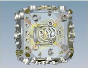
EMC2 (Polywell Fusion) has updated their site with an image of WB-8 shown above. The Drawing is labeled as "with diagnostics".
And then there is this picture:

Labeled:
WB-D 100MW Polywell Demo DeviceThere is considerable speculation at Talk Polywell as to what it all means.
Your Contributions Will Help Us Design The WB-D Polywell Device
Send your supporting contributions to:
New Mexico Community Foundation
Contact Energy Matter Conversion Corporation
1202 Parkway Drive Suite A
Santa Fe, NM 87507
Phone: 505-471-2050
Email: Rick at Emc2fusion dot com
And since from time to time there are people reading here who need to be brought up to speed on fusion I'm reposting my usual: You can learn the basics of fusion energy by reading Principles of Fusion Energy: An Introduction to Fusion Energy for Students of Science and Engineering
Polywell is a little more complicated. You can learn more about Polywell and its potential at: Bussard's IEC Fusion Technology (Polywell Fusion) Explained
The American Thinker has a good article up with the basics.
And the best part? We Will Know In Two Years or less.
I'm a big fan of small fusion projects. Especially after hearing what Plasma Physicist and author of Principles of Plasma Physics
Update:
Here is the progress report given so far by EMC2:
EMC2 Fusion Development Corporation has been formed as a charitable research and development organization in frontier energy technologies with emphasis on fusion.Good luck and happy fusing to the EMC2 folks and Rick Nebel who is leading the project.
Fusion R&D Phase 1 - Validate and extend WB-6 results with WB-7 Device: 1.5 years / $1.8M, Successfully Completed
Fusion R&D Phase 2 - Design, build and test larger scale WB-8 Polywell Device: 2 years / $7M, In Process
Fusion R&D Phase 3 - Design, build and test full scale 100 MW Fusion System: 4 years / $200M, In Design Phase
Successful Phase 3 marks the end of fossil fuels
Friday, March 12, 2010
Venture Capital Likes Fusion
If you read my post Investing In Polywell you would know that venture capital seems interested in funding fusion start-ups. We now have more confirmation in this Finance Business article.
Let me also say that I have been approached several times over the last few years to personally develop a project that would reach the fusion goal faster than any government project. One of these days I will connect either with my own project or as an assistant to some one else's project.
A prominent venture capitalist, Wal van Lierop, of Chrysalix Energy Venture Capital, has begun to invest in companies (such as General Fusion) who are providing patents and technologies for economical fusion power. in a recent interview at the Clean Tech Investor Summit (which we're very sad we're not attending), van Lierop said that he expects large energy companies to start thinking about building fusion plants within the next five years.Yes. It does seem remarkable. Except if you have been reading articles of mine like: We Will Know In Two Years or less. Or one of my more recent ones like: Advanced and Delayed.
As we've noted before here at EcoGeek, the best way to track down that technologies are going to (very shortly) change the world is to watch what the venture capitalists are doing. these are people who basically make ridiculous sums of cash by predicting the future...and investing in it. and since they've got so much riding on their bets, they like to do a lot of research.
Often this is research that people like me (because I don't have billions of dollars to invest) can't do. So I follow the VCs, and pay attention to what they're saying.
And what van Lierop is saying seems almost crazy, on the surface. But dig a little deeper, and things start looking exciting. despite sounding like a comic book hero, General Fusion's technology is very realistic. in a world where we're all used to hearing that "Fusion power has been twenty years away for twenty years" hearing that it's five years away is pretty remarkable.
Let me also say that I have been approached several times over the last few years to personally develop a project that would reach the fusion goal faster than any government project. One of these days I will connect either with my own project or as an assistant to some one else's project.
Wednesday, March 10, 2010
Investing In Polywell
Famulus at Prometheus Fusion had a close encounter with an angel investor from Europe. He gives an account of his interactions. Famulus was kind enough to ask me for some assistance with his proposal. I also got one of my physicist friends (Dr. Mike) to help out.
Famulus needs to raise funds to continue his experiments. He is getting close to his goal.
Donate Here.
Famulus needs to raise funds to continue his experiments. He is getting close to his goal.
Donate Here.
Wednesday, February 17, 2010
Open Source With Superconductors
My friend Famulus is building an open source Polywell with super Conducting magnets. It would be the first superconducting Polywell in the world as far as anyone knows. Follow the link to see pretty pictures of the plan.
Here he discusses power supplies for the coils.
All very impressive. I wish I was there. There is a slight hitch. Famulus has run into a money problem.
As of the last time I checked he had 25 donations and only needs $1,958 to reach is goal. You can check his latest fund raising stats and donate at the link. And click on the "Updates" link at the top of the page. There are 6 of them.
But that is not the only motivational trick he has in his bag. He has custom T shirts too! I think he needs a better slogan for the shirt. Maybe I Helped Fund An Open Source Bussard Fusion Reactor And Got The Shirt As A Bonus. With suitable type faces.
And just in case you haven't heard of Polywell I can bring you up to speed. You can learn the basics of fusion energy by reading Principles of Fusion Energy: An Introduction to Fusion Energy for Students of Science and Engineering
Polywell is a little more complicated. You can learn more about Polywell and its potential at: Bussard's IEC Fusion Technology (Polywell Fusion) Explained
The American Thinker has a good article up with the basics.
And the best part? We Will Know In Two Years or less.
I'm a big fan of small fusion projects. Especially after hearing what Plasma Physicist and author of Principles of Plasma Physics Dr. Nicholas Krall said, "We spent $15 billion dollars studying tokamaks and what we learned about them is that they are no damn good." No I'm not against ITER, totally, but it is sucking all the oxygen out of the room. For a project that will not be done (regular power production) for 40 to 70 more years. With that kind of schedule we can afford to wait for some breakthroughs.
Oh yeah.
Pledge Some Money to help keep amateurs on the cutting edge.
Here he discusses power supplies for the coils.
All very impressive. I wish I was there. There is a slight hitch. Famulus has run into a money problem.
As of the last time I checked he had 25 donations and only needs $1,958 to reach is goal. You can check his latest fund raising stats and donate at the link. And click on the "Updates" link at the top of the page. There are 6 of them.
But that is not the only motivational trick he has in his bag. He has custom T shirts too! I think he needs a better slogan for the shirt. Maybe I Helped Fund An Open Source Bussard Fusion Reactor And Got The Shirt As A Bonus. With suitable type faces.
And just in case you haven't heard of Polywell I can bring you up to speed. You can learn the basics of fusion energy by reading Principles of Fusion Energy: An Introduction to Fusion Energy for Students of Science and Engineering
Polywell is a little more complicated. You can learn more about Polywell and its potential at: Bussard's IEC Fusion Technology (Polywell Fusion) Explained
The American Thinker has a good article up with the basics.
And the best part? We Will Know In Two Years or less.
I'm a big fan of small fusion projects. Especially after hearing what Plasma Physicist and author of Principles of Plasma Physics
Oh yeah.
Pledge Some Money to help keep amateurs on the cutting edge.
Monday, February 8, 2010
ITER Image Trouble

The above Image is from the top of this page. It is a working fusor grid working in star mode. In other words the image is from an IEC device not a tokamak device.
Maybe it is a subtle sign the tokamak folks are losing hope.
H/T chrismb at Talk Polywell.
Saturday, February 6, 2010
Shake Up On The Way
For those of you not familiar with Latin "iter" means "the way". And the ITER Fusion program now headquartered in France is undergoing a top management shake up.
And let me leave you with a few words from a Polywell Fusion fan who is no fan of Tokamak designs (ITER and similar devices): Plasma Physicist and author of Principles of Plasma Physics Dr. Nicholas Krall said, "We spent $15 billion dollars studying tokamaks and what we learned about them is that they are no damn good."
And the best thing about Polywell is what Physicist Rick Nebel, who is now herding the project, has to say about it: We Will Know In Two Years or less.
In an effort to put the world's largest scientific experiment back on track after delays and cost overruns, Europe is shaking up the agency overseeing its portion of the multinational ITER reactor.It seems the shake up is due in part to unhappy customers. You know - the people putting up the money.
On 16 February, Frank Briscoe, a British fusion scientist, will take the reins as interim director of Fusion for Energy (F4E), the agency in Barcelona, Spain, that manages Europe's ITER contribution — the largest of any partner's. Briscoe replaces Didier Gambier, a French physicist who joined the F4E as director when it formed in 2007. Gambier was originally appointed for a five-year term.
The European Union (EU) is also formulating a plan to complete construction on the multibillion-dollar machine in 2019, a year after currently scheduled, Nature has learned.
ITER aims to prove the viability of fusion power by using superconducting magnets to squeeze a plasma of heavy hydrogen isotopes to temperatures above 150 million °C. When full-scale experiments begin in 2026, the machine should produce ten times the power it consumes.
Europe has faced increasing criticism from ITER's six other international partners: Japan, South Korea, Russia, India, China and the United States. A budget proposed last week by US president Barack Obama would slash America's funding for ITER in 2011 by 40%, to US$80 million; it cited "the slow rate of progress by the [ITER Organization] and some Members' Domestic Agencies". And on 2 February, Evgeny Velikhov, a Russian fusion researcher and head of ITER's council, called Europe a "weak link". "Unfortunately, their organizational structure is very poor," he told Russian President Vladimir Putin in an interview that appeared on a Russian government website.In a recent post, Spiraling Out Of Control, I discussed some of the financial problems at ITER. And for those of you interested in the technical problems may I suggest (actually highly recommend) the Talk Polywell link at the end of that article.
Finishing ITER in 2019, a goal that the F4E is now working towards with industrial contractors, would involve risks such as producing components in parallel, but scientists think that those risks can be managed. "There should be no doubt that Europe is trying hard to get ITER ready in the shortest time that is realistic," says one senior European scientist. The new schedule will be presented to other ITER partners at a meeting on 23–24 February in Paris.
And let me leave you with a few words from a Polywell Fusion fan who is no fan of Tokamak designs (ITER and similar devices): Plasma Physicist and author of Principles of Plasma Physics
And the best thing about Polywell is what Physicist Rick Nebel, who is now herding the project, has to say about it: We Will Know In Two Years or less.
Thursday, February 4, 2010
Spiraling Out Of Control
I have covered the troubles the ITER fusion project is having in ITER Gets Clipped which covered the American view of ITER's troubles. The The European Voice is taking a look at the problems from an European view.
Interesting that the budget was low balled to get things going and then things started spiraling out of control. Making up for missing resources in out years always costs a lot more than budgeting for them from the start. We see this in the space program all too often. The reason is that you have people you have to keep on board while changes are being made. What we in engineering like to refer to as "the burn rate" - the amount you have to spend to keep going while actual progress halts to make the changes. Every day's delay can cost millions of dollars. Then there is the problem of bringing new people up to speed. Adding people to a late project will often increase the delay over what making do with the people you have will cause. It is easy to get into a regenerative mode where you can never finish at an acceptable time with an acceptable budget. Another thing that happens when you add new people to a project is that the design suffers because the new people never know as much as the old hands.
Fredrick Brooks originally looked at this problem with respect to big software projects. He published his observations in a 1975 book called The Mythical Man-Month: Essays on Software Engineering.
It is probably the best book on big project management ever written so far. I have used his insights often in my engineering career. Management will hardly ever listen to these types of insights at the beginning. But occasionally you can get them to accept the insights provided once a project is in trouble.
Let me add that the much smaller Polywell Fusion project is not having any such difficulty. Physicist Rick Nebel said of his WB-7 experiment: it "runs like a top". Rick has been mum about WB-8 progress. Since he has the same team that did WB-7 working on WB-8, I expect he will deliver the knowledge required on time and within budget. Of course he has an advantage. It is easier to keep a small project ($ millions) on time than it is to do the same for a large project ($ billions). If the experiments look promising I expect that he will have a lot more trouble getting a real power plant operational. The logistics get harder.
You can look at recent list of the design problems ITER faces at Talk Polywell.
ITER's projected costs have soared since the first estimates were made in 2001. Contributions will generally be made in kind (through provisions of construction materials, reactor components, labour and expertise). The EU's total in-kind contribution was estimated at €1.491 billion in 2001. By 2008, when the EU's Fusion for Energy agency, which was set up to manage the EU contribution to ITER, reviewed the costs, the estimate had risen to €3.5bn.The latest budget numbers I have seen have the project estimate at around $7 billion US (€5.1 billion).
Rising costs
Concerns about the ballooning budget led the Commission last year to set up an expert group tasked with reviewing the construction costs. The group's report, released to member states last month and seen by European Voice, said that the construction costs alone could rise as high as €1.5bn (compared to a 2001 estimate of €598 million).
The report said that the increase was a result of “omissions or underestimates” in the original estimates, inflation in concrete and steel prices and “changes in specifications”.
The Commission has set up a task-force to identify sources of additional funding for ITER. One option being considered is a loan from the European Investment Bank.
Interesting that the budget was low balled to get things going and then things started spiraling out of control. Making up for missing resources in out years always costs a lot more than budgeting for them from the start. We see this in the space program all too often. The reason is that you have people you have to keep on board while changes are being made. What we in engineering like to refer to as "the burn rate" - the amount you have to spend to keep going while actual progress halts to make the changes. Every day's delay can cost millions of dollars. Then there is the problem of bringing new people up to speed. Adding people to a late project will often increase the delay over what making do with the people you have will cause. It is easy to get into a regenerative mode where you can never finish at an acceptable time with an acceptable budget. Another thing that happens when you add new people to a project is that the design suffers because the new people never know as much as the old hands.
Fredrick Brooks originally looked at this problem with respect to big software projects. He published his observations in a 1975 book called The Mythical Man-Month: Essays on Software Engineering.
It is probably the best book on big project management ever written so far. I have used his insights often in my engineering career. Management will hardly ever listen to these types of insights at the beginning. But occasionally you can get them to accept the insights provided once a project is in trouble.
Let me add that the much smaller Polywell Fusion project is not having any such difficulty. Physicist Rick Nebel said of his WB-7 experiment: it "runs like a top". Rick has been mum about WB-8 progress. Since he has the same team that did WB-7 working on WB-8, I expect he will deliver the knowledge required on time and within budget. Of course he has an advantage. It is easier to keep a small project ($ millions) on time than it is to do the same for a large project ($ billions). If the experiments look promising I expect that he will have a lot more trouble getting a real power plant operational. The logistics get harder.
You can look at recent list of the design problems ITER faces at Talk Polywell.
Tuesday, February 2, 2010
ITER Gets Clipped
It looks like the Obama Administration is cutting back its support for ITER in next year's Federal Energy Budget.
...funding for DOE’s fusion energy sciences (FES) program gets clipped from an estimated $426 million this year to a requested $380 million next year, a reduction of 10.8%. That reduction would come out of the United States’s contribution to the international fusion experiment, ITER, which will be built in Cadarache, France. Under the proposed budget, ITER would get $80 million next year, down from an estimated $135 million this year. The decrease marks the latest dip on the ITER budget roller coaster. In 2008, Congress zeroed out $150 million of spending on ITER in a squabble with the White House. The project got $124 million the following year.I looked at the ongoing design review in ITER Back To The Drawing Board. I believe ITER is in big trouble for two reasons. One is that the engineering is not solid even for an experimental project and also that even if it is successful in its 40 or 50 year time line it will never produce a commercially viable fusion reactor.
Ironically, the current cut comes about because ITER itself has slowed down as researchers contend with design revisions that could double its $7 billion price tag. “We need to make sure that we don’t get ahead of the project as a whole,” says Thom Mason, director of Oak Ridge National Laboratory in Tennessee, home of the U.S. ITER project office. The proposed $80 million would keep U.S. researchers fully engaged next year, Mason says. However, he worries that the dip this year will make the required funding increases in 2012 and beyond all the larger and harder to achieve.
Wednesday, January 27, 2010
New IEC Fusion Research Group Opens
Space Ports reports the opening of an IEC Fusion Research facility to develop fusion for spacecraft propulsion.
Whose work is this based on? George Miley who I mentioned in A New Theory Of Electrodynamics. A look at the AVR page on fusion has some more hints.
AVR has a slide show in pdf of their design. It is a variant of a Farnsworth Fusor operating with 600 to 800 volt drive which will burn Hydrogen and Boron 11. I wonder how they plan to make it work with such low drive voltages? Perhaps their plan to begin with a Deuterium-Helium 3 fuel has something to do with it.
This paper [pdf} indicates that they are planning to use the IEC design as just a thruster to start with.
Kind of like the progression in piston pump technology. First you build pumps. Very handy. Then you apply steam and pumps become a power source. Then you figure out how to burn the fuel inside the cylinder and you get an internal combustion engine. Let's hope we can compress the development cycle from hundreds of years to a couple of decades.
Update: 1934z 29 Jan 2010
Next Big Future has more.
AVRC has been awarded a contract by Wise County's Industrial Development Authority to manage a $7 million energy research center now under construction in the Lonesome Pine Business and Technology Park [PDF] in Wise, VA focused on the development of inertial electrostatic confinement aneutronic fusion energy at the Appalachia America Energy Research Center along with other projects in a significant energy technology portfilio.That is interesting.
Plans are in the works to conduct a multimillion-dollar research project in Wise to develop fusion technology into a cheap source for everything from electricity to spacecraft propulsion. Invented by the University of Illinois at Urbana-Champaign's Dr. George Miley, the process involves pumping aerosol boron plasma into a spherical container where it is made very, very hot. The atoms begin to fuse, creating energy.
The project will start small, with about 6-8 researchers, and could employ 20-28 researchers within 18 months.
Whose work is this based on? George Miley who I mentioned in A New Theory Of Electrodynamics. A look at the AVR page on fusion has some more hints.
The Intertial Electrostatice Confinement (IEC) Fusion Propulsion technology being promoted by AVRC was developed by Dr. George Miley.I wonder how they plan to fuse hydrogen which is very difficult to fuse because it requires converting a proton into a neutron to make the reaction work. Or maybe they just plan to use hydrogen gathered in space as reaction mass and plan to fuse something else. Sort of like a modified Bussard Ramjet.
Fusion reactions release an enormous amount of energy which is why there is such a large push for research in harnessing the energy for propulsion systems. A fusion propulsion system could have a specific impulse about 300 times greater than a conventional chemical rocket engine. Fusion-powered rockets would use hydrogen as a propellant, which means it would be able to replenish itself as it travels through space.
AVR has a slide show in pdf of their design. It is a variant of a Farnsworth Fusor operating with 600 to 800 volt drive which will burn Hydrogen and Boron 11. I wonder how they plan to make it work with such low drive voltages? Perhaps their plan to begin with a Deuterium-Helium 3 fuel has something to do with it.
This paper [pdf} indicates that they are planning to use the IEC design as just a thruster to start with.
A novel plasma jet thruster, based on Inertial Electrostatic Confinement (IEC) technology, is proposed for ultra maneuverable - space thruster for satellite and small probe thrust operations. The IEC Jet design potential offers an unique capability to cover a wide range of powers (few Watts to Kilowatts) with good efficiency while providing a plasma jet that can start with a large diameter but be narrowed directionally to focus on targets The IEC thruster uses a spherical configuration, wherein ions are generated and accelerated towards the center of a spherical vacuum chamber A virtual cathode forms in the high-density central core region, combined with a locally distorted cathode grid potential field, extracts accelerated ions into an intense quasi-neutral ion jet. Thus, the IEC thruster is roughly analogous to a planar electrostatic ion thruster "folded" into spherical form. Estimates suggest that its electrical efficiency would match conventional plasma thrusters, while offering advantages in design simplicity, reduced erosion giving long life time, reduced propellant leakage losses, and high power-to-weight ratio. Heat rejection is eased due to large heated surface areas making the unit especially well suited to high power operation.That might work. And if it does fusion could come later.
Kind of like the progression in piston pump technology. First you build pumps. Very handy. Then you apply steam and pumps become a power source. Then you figure out how to burn the fuel inside the cylinder and you get an internal combustion engine. Let's hope we can compress the development cycle from hundreds of years to a couple of decades.
Update: 1934z 29 Jan 2010
Next Big Future has more.
A New Theory Of Electrodynamics
I have just sent this out to a group of physicists and scientists to see if it has any merit.
Here is the cover letter I sent:
George Miley of U Illinois, Champaign is involved.It will be interesting if anything comes of it.
I am passing this on after a cursory review. It was published yesterday. Please give it 5 minutes before you give up. The speed of light bit in the beginning was off putting for me. But it gets explained better later. The equations at first glance are compelling. They are better covered in the second 5 minutes. I'm going to review it more carefully with multiple stops to get a better feel. This is rapid fire and not typical lecture speed.
I'm more at home with engineering but I am at least conversant with all the material presented. I have also introduced the video to Lubos Motl to see what he thinks.
Here are some of the documents in the video:
Evidence of Cold Fusion?
Impulse Gravity Generator?
Gravitomagnetic Field of a Rotating Superconductor
and of a Rotating Superfluid [pdf]
Researchers now able to stop, restart light
The Control of the Natural Forces by Frank Znidarsic [pdf]
BBC News - Boeing tries to defy gravity
Quantum Chemistry - McQuarrie
http://www.cravenslab.org
Tapping the Zero Point Energy
H/T jlumartinez at Talk Polywell
Saturday, January 16, 2010
Nerd Night Report
Here is the first sketchy report on last night's nerd night in New York.
If you've never been to a Nerd Nite before, here's how it goes down. Take a college PowerPoint seminar on bird migration or muscular dystrophy or nuclear fusion or what have you, and hold it late at night in a hip bar in DUMBO. Allow anyone to present on any scientific subject, regardless of obscurity, social appropriateness, or sobriety. Yes. It is exactly as crazy and surreal as you imagine. And it is great.Here is my original announcement of Nerd Night with fusion.
Tonight's lectures were on open source Bussard reactors, the neuroscience of visual perception in the context of art, the anti-ergonomic effects of running shoes, and teledildonics. I think you can probably imagine how each of those went.
Perhaps most notably, this is the first large social event I've been to in NYC in which I've actually succeeded in getting to meet and hang out with random strangers in my general age cohort. Maybe I don't completely suck at making new friends after all.
I missed nerds so much.
Tuesday, January 12, 2010
Nerd Night
Famulus of Prometheus Fusion will be featured at Nerd Night, Friday, January 15th, in NYC.
Polywell is a little more complicated. You can learn more about Polywell and its potential at: Bussard's IEC Fusion Technology (Polywell Fusion) Explained
The American Thinker has a good article up with the basics.
And the best part? We Will Know In Two Years
*Presentation 1If you have the time and the inclination a night out with the nerds could be fun. And if you want learn the basics of fusion energy so you can ask intelligent questions you can start by reading Principles of Fusion Energy: An Introduction to Fusion Energy for Students of Science and Engineering
Fusing the Atom and Living to Tell
by Famulus
Description: We have built an open source nuclear fusion reactor and fused the atom. This is the story of a remarkable fusion device called the Farnsworth Fusor and its successor, the Bussard Reactor (aka. Polywell). The Bussard Reactor holds the promise of clean cheap abundant energy from fusion. This is a story of research on the edge.
Bio: Famulus is an entrepreneur, hacker, and rails developer. In 2008 he learned of the Bussard fusion reactor and left the software world to try and build a working Bussard Reactor.
Polywell is a little more complicated. You can learn more about Polywell and its potential at: Bussard's IEC Fusion Technology (Polywell Fusion) Explained
The American Thinker has a good article up with the basics.
And the best part? We Will Know In Two Years
Sunday, January 3, 2010
The University of Sydney Is Building Small Polywell
Prometheus Fusion reports that the University of Sydney is building a small Polywell with copper coils.
He has picture and a link to a series of Power Point slides explaining the work.
He has picture and a link to a series of Power Point slides explaining the work.
Friday, December 18, 2009
IEC 2009 - Wisconsin
Friday, December 4, 2009
The Current State Of Fusion
Alan Boyle at Cosmic Log has the latest broad look at the state of Fusion. He discusses the state of laser fusion. The the $3.5 billion American National Ignition Facility seems to be doing well. But what excites me is that he has some indirect news on The Polywell Fusion Reactor experiments.
As you know I have been closely following the progress of the WB-X contracts at EMC2. If you want to get deeper into them:
WB-8 Contract Progress
Polywell Gets The Dough
The Boys At Talk-Polywell Have Struck Paydirt
WB-8 In The Works
Polywell Gets In On The Act
You can learn the basics of fusion energy by reading Principles of Fusion Energy: An Introduction to Fusion Energy for Students of Science and Engineering
Polywell is a little more complicated. You can learn more about Polywell and its potential at: Bussard's IEC Fusion Technology (Polywell Fusion) Explained
The American Thinker has a good article up with the basics.
And the best part? We Will Know In Two Years
H/T rschaffer8 at Talk Polywell
The dark horse in the fusion race is an approach known as inertial electrostatic confinement fusion, or Polywell fusion. This method, pioneered by the late physicist Robert Bussard, involves designing a high-voltage cage in such a way that atomic nuclei slam into each other at high speeds, sparking fusion.That is the hope. Now what about some news?
In September, EMC2 Fusion was awarded a Navy contract, backed by $7.9 million in stimulus funds, to develop a scaled-up version of a Polywell fusion reactor. Development and testing of the device is expected to take two years, and there's an option to spend another $4.4 million on experiments with hydrogen-boron fuel (known as pB11).My sources on the project have dried up as well. No one is talking. I am running on unsupported rumors and conjecture. Some think that the silence is a cover up for failure. Being a fanboy I'm more inclined that they are so wildly successful that the Navy doesn't want to let the cat out of the bag any sooner than they can help. Reality is probably some where in the middle or worse. The design is so simple that if the Navy gets it to work no country is more than 5 years behind in producing a working model from scratch (given a crash program).
In the past, EMC2 Fusion's Richard Nebel has been able to describe the team's progress in general terms, saying that he was "very pleased" with the performance of an earlier test device. But now, with more Navy money on the line, Nebel has been constrained from saying anything about the project. The fact that the research is continuing, however, appears to indicate that the results have been promising enough to keep the Navy interested.
As you know I have been closely following the progress of the WB-X contracts at EMC2. If you want to get deeper into them:
WB-8 Contract Progress
Polywell Gets The Dough
The Boys At Talk-Polywell Have Struck Paydirt
WB-8 In The Works
Polywell Gets In On The Act
You can learn the basics of fusion energy by reading Principles of Fusion Energy: An Introduction to Fusion Energy for Students of Science and Engineering
Polywell is a little more complicated. You can learn more about Polywell and its potential at: Bussard's IEC Fusion Technology (Polywell Fusion) Explained
The American Thinker has a good article up with the basics.
And the best part? We Will Know In Two Years
H/T rschaffer8 at Talk Polywell
Tuesday, December 1, 2009
ITER Back To The Drawing Board
The ITER fusion test reactor project is getting a schedule review [pdf] because the project is seriously out of whack.
I wonder if the fact that Focus Fusion, and Tri-Alpha Energy, and General Fusion, and other groups promise results much sooner at much lower costs also has something to do with the reevaluation.
Of course you all know my favorite. The Polywell Fusion Reactor. You can learn the basics of fusion energy by reading Principles of Fusion Energy: An Introduction to Fusion Energy for Students of Science and Engineering
Polywell is a little more complicated. You can learn more about Polywell and its potential at: Bussard's IEC Fusion Technology (Polywell Fusion) Explained
The American Thinker has a good article up with the basics. And the best part? We Will Know In Two Years.
Here is a good page to keep up with ITER news. I love what it says at the top of the page:
18 Years Until 1st Q = 10 DT pulse 400s long at 500MW on ITER
Plasma Physicist and author of Principles of Plasma PhysicsDr. Nicholas Krall said, "We spent $15 billion dollars studying tokamaks and what we learned about them is that they are no damn good."
The scientific and engineering team building the ITER fusion reactor failed to win an expected endorsement from the project’s governing council last week. The council, which represents the seven international partners in the project—China, the European Union, India, Japan, South Korea, Russia, and the United States—sent the team back to do more work on the proposed construction schedule for the mammoth undertaking.So what is being done to fix this mismatch between means and ends?
...ITER staff have been racing for months to get the final project baseline documents, which describe the design, cost estimates, and planned schedule, ready for the 18–19 November council meeting at Cadarache (Science, 13 November, p. 932). But some council members voiced concern that the schedule, which aimed to start the reactor by 2018, was not realistic and that there was too high a risk that some part of the immensely complicated effort could go wrong.And they are not even going to discuss costs until they get a schedule estimate. Good.
A slip in the schedule would invariably mean increased costs, and the council is already concerned about budget estimates, which, sources say, may have doubled from 5 billion since the partners signed up in 2006. So the council told ITER staff to nail down more firmly the risks, both technical and organizational, involved in the schedule and come back in February with earliest and latest possible start-up dates.
I wonder if the fact that Focus Fusion, and Tri-Alpha Energy, and General Fusion, and other groups promise results much sooner at much lower costs also has something to do with the reevaluation.
Of course you all know my favorite. The Polywell Fusion Reactor. You can learn the basics of fusion energy by reading Principles of Fusion Energy: An Introduction to Fusion Energy for Students of Science and Engineering
Polywell is a little more complicated. You can learn more about Polywell and its potential at: Bussard's IEC Fusion Technology (Polywell Fusion) Explained
The American Thinker has a good article up with the basics. And the best part? We Will Know In Two Years.
Here is a good page to keep up with ITER news. I love what it says at the top of the page:
18 Years Until 1st Q = 10 DT pulse 400s long at 500MW on ITER
Plasma Physicist and author of Principles of Plasma Physics
Saturday, November 28, 2009
Tom Ligon On Space Show
Tom Ligon is going to be on the Space Show this Sunday from 12 to 1:30 PDT. You can call in or listen. Information at the link.
Update: 29 Nov 2009 2020z
I had my dates mixed up. Tom will be on the Space Show for Tuesday evening, December 22, 7-8:30 PM California time. There is a good chance I will be on the show as well.
Update: 29 Nov 2009 2020z
I had my dates mixed up. Tom will be on the Space Show for Tuesday evening, December 22, 7-8:30 PM California time. There is a good chance I will be on the show as well.
Sunday, November 22, 2009
Designing Computer Chips
My latest article at ECN discusses how to design computers in the context of FORTH chips.
Friday, November 20, 2009
First Fusion
Prometheus Fusion has announced his first fusion neutron.
Drop by and give him an atta boy.
H/T Talk Polywell
Drop by and give him an atta boy.
H/T Talk Polywell
Sunday, October 25, 2009
The DOD Looks At Energy Security
The gentlemen and gentlewomen at Talk Polywell have come across a couple of major finds. The first is a discussion of American energy security and its military implications. Energy & National Security: An Exploration of Threats, Solutions, and Alternative Futures [pdf].
The second paper is about funding for various quick reaction [pdf] programs by the DOD. The interesting bits are on page 11 of the document. Look at just how small the effort was in fiscal year 2008.
You can learn the basics of fusion energy by reading Principles of Fusion Energy: An Introduction to Fusion Energy for Students of Science and Engineering
Polywell is a little more complicated. You can learn more about Polywell and its potential at: Bussard's IEC Fusion Technology (Polywell Fusion) Explained
The American Thinker has a good article up with the basics.
Abstract – Findings of multiple Department of Defense (DoD) studies and other sources indicate that the United States faces a cluster of significant security threats caused by how the country obtains, distributes, and uses energy. This paper explores the nature and magnitude of the security threats as related to energy—some potential solutions, which include technical, political, and programmatic options; and some alternative futures the nation may face depending upon various choices of actions and assumptions. Specific emerging options addressed include Polywell fusion, renewable fuel from waste and algae cultivation, all-electric vehicle fleets, highly-efficient heat engines, and special military energy considerations.Interesting (to say the least) that Polywell gets a mention in the very beginning of the paper. We have come a long way since the Polywell program was nearly permanently shut down in 2006.
The second paper is about funding for various quick reaction [pdf] programs by the DOD. The interesting bits are on page 11 of the document. Look at just how small the effort was in fiscal year 2008.
EMC2/IEFThings are picking up speed in the Polywell research. You can find out more about the latest funding for Polywell at WB-8 Contract Details and at WB-8 Contract Progress.
Boron Fusion The objective of this project is to continue research towards a proven, validated, and reviewed and approved final design basis for engineering development and construction of full-scale clean nuclear power plants. Boron/hydrogen reactions are radiation-free and non-hazardous and well-suited to direct electric power applications to Navy propulsion, as well as to modest scale ground power plants/systems, able to be run without fossil fuels. Such power plants would revolutionize DoD power systems applications and requirements.
FY 2008 Accomplishments:
This project continued research towards a proven, validated, and reviewed and approved final design basis for engineering development and construction of full-scale clean nuclear power plants. Payoff would be elimination of the need for fossil fueled plants. Boron/hydrogen reactions are radiation-free and non-hazardous and well-suited to direct electric power applications to Navy propulsion, as well as to modest scale ground power plants/systems, able to be run without fossil fuels. Such power plants would revolutionize DoD power systems applications and requirements.
You can learn the basics of fusion energy by reading Principles of Fusion Energy: An Introduction to Fusion Energy for Students of Science and Engineering
Polywell is a little more complicated. You can learn more about Polywell and its potential at: Bussard's IEC Fusion Technology (Polywell Fusion) Explained
The American Thinker has a good article up with the basics.
Thursday, October 22, 2009
Mach-Einstein Drive
I have a new article up at ECN Magazine on experiments testing out the possibilities of a Mach-Einstein Drive. I call it: Maching Einstein.
Why is this important? If the experiments work (and even if they don't) we will learn more about how our universe is constructed. If they do work we can get propulsion without having to build huge rockets. Earth to Mars travel in a few days would be a definite possibility. If it works really really well faster than light speed travel is a definite possibility.
Why is this important? If the experiments work (and even if they don't) we will learn more about how our universe is constructed. If they do work we can get propulsion without having to build huge rockets. Earth to Mars travel in a few days would be a definite possibility. If it works really really well faster than light speed travel is a definite possibility.
Tuesday, October 6, 2009
Sunday, October 4, 2009
WB-8 Contract Progress
The US Navy has just published a Justification and Award for EMC2's Polywell Fusion Reactor experiment.
The highlights:
* The award is for $10 million
* WB-8.0 report to be delivered 30 March 2010
* WB-8.1 report to be delivered 30 March 2012
The WB-8.1 effort is contingent on success with WB-8.0 experiments.
What does all this mean? It is possible that there has been much more progress than was expected. You can read about the expected progress at: We Will Know In Two Years. That was published in May of 2009. The minimum time expected for results when that was published was 18 months which would have been November of 2010. Actual time from the prediction to the end of the WB-8.0 contract is 10 months. Of course this is speculative. It may be that we won't know until March of 2012. Which would make the actual time line almost three years and not two.
You can read some of my previous posts on the WB-8 contract at:
Polywell Gets The Dough
The Boys At Talk-Polywell Have Struck Paydirt
WB-8 In The Works
And if you are not familiar with fusion in general or Polywell in particular may I suggest:
Principles of Fusion Energy: An Introduction to Fusion Energy for Students of Science and Engineering
Polywell is a little more complicated. You can learn more about Polywell and its potential at: Bussard's IEC Fusion Technology (Polywell Fusion) Explained
The American Thinker has a good article up with the Polywell basics.
Tuesday, September 22, 2009
Major Electronics Magazine Covers Polywell
ECN Magazine has an article up on Polywell and other small fusion efforts. You will never guess who the author is. Heh.
Saturday, September 12, 2009
Polywell Gets The Dough
EMC2 has gotten almost eight million dollars to do further experimentation on the Polywell Fusion concept.
Evidently the $2 million promised in May was just a place holder and the actual funds are significantly greater. This means that the work on WB-8 and the engineering for WB-9 will go forward with the next milestone in April of 2011. Which is in accord with Rick Nebel's promise that We Will Know In Two Years.
If you would like to keep these reports coming visit Five Years of Blogging and do what you can.
You can learn the basics of fusion energy by reading Principles of Fusion Energy: An Introduction to Fusion Energy for Students of Science and Engineering
Polywell is a little more complicated. You can learn more about Polywell and its potential at: Bussard's IEC Fusion Technology (Polywell Fusion) Explained
The American Thinker has a good article up with the basics.
H/T Marc Bruggeman via e-mail.
Thanks to Instapundit for the link!
Update: 14 Sept. 2009 22:59z
There is new information about the award:
Energy Matter Conversion Corp., (EMC2)*, Santa Fe, N.M., is being awarded a $7,855,504 cost-plus-fixed-fee contract for research, analysis, development, and testing in support of the Plan Plasma Fusion (Polywell) Project. Efforts under this Recovery Act award will validate the basic physics of the plasma fusion (polywell) concept, as well as provide the Navy with data for potential applications of polywell fusion. Work will be performed in Santa Fe, N.M., and is expected to be completed in April 2011. Contract funds will not expire at the end of the current fiscal year. This contract was not competitively procured pursuant to FAR 6.302-1. The Naval Air Warfare Center Weapons Division, China Lake, Calif., is the contracting activity (N68936-09-C-0125).I think this is the award based on the solicitation discussed here and here and here.
Evidently the $2 million promised in May was just a place holder and the actual funds are significantly greater. This means that the work on WB-8 and the engineering for WB-9 will go forward with the next milestone in April of 2011. Which is in accord with Rick Nebel's promise that We Will Know In Two Years.
If you would like to keep these reports coming visit Five Years of Blogging and do what you can.
You can learn the basics of fusion energy by reading Principles of Fusion Energy: An Introduction to Fusion Energy for Students of Science and Engineering
Polywell is a little more complicated. You can learn more about Polywell and its potential at: Bussard's IEC Fusion Technology (Polywell Fusion) Explained
The American Thinker has a good article up with the basics.
H/T Marc Bruggeman via e-mail.
Thanks to Instapundit for the link!
Update: 14 Sept. 2009 22:59z
There is new information about the award:
Research Development Test Evaluation (RDT&E) Plan Plasma Fusion (Polywell) project. The Naval Air Warfare Center Weapons Division, China Lake has awarded a Cost Plus Fixed Fee contract for research, analysis, development, and testing to validate the basic physics of the plasma fusion (polywell) concept as well as requirements to provide the Navy with data for potential applications of polywell fusion with a delivered item, wiffleball 8 (WB8) and options for a modified wiffleball 8 (WB8.1) and modified ion gun. The requirement is sole sourced to Energy/Matter Conversion Corporation (EMC2) who is the original developer of the plasma fusion (polywell) approach and holds the proprietary data rights. The address for EMC2 is 1202 Parkway Dr, STE A, Santa Fe, NM 87507-7253. Award includes an option for a Wiffleball 8.1 for an additional $4,455,077.By dividing up the contract this way there are probably milestones that need to be met before further work is authorized.
Sunday, August 23, 2009
A Word For The Sceptics
I was looking at the comments to my American Thinker article Fusion Energy and came across an interesting sequence of comments I had missed earlier. The first comment is by a sceptic. There are earlier comments by him in the comment section.
And what is Rick's time frame? The answer Rick gives is "We Will Know In Two Years."
You can learn the basics of fusion energy by reading Principles of Fusion Energy: An Introduction to Fusion Energy for Students of Science and Engineering
Polywell is a little more complicated. You can learn more about Polywell and its potential at: Bussard's IEC Fusion Technology (Polywell Fusion) Explained
The American Thinker has a good article up with the basics. (same article referenced above)
Why hasn't Polywell Fusion been fully funded by the Obama administration?
Posted by: WR Jonas Jun 19, 01:18 PMI added the emphasis. And then there is a reply to the question by Rick Nebel:
I have spoken out here about my skepticism based on a provable dynamic and truth. There will always be ample reasons to spend other peoples money. To give this research or any other some noble purpose or cause does not necessarily make the aims correct or worthwhile.
If we were still shooting rockets at the moon and coming up empty or failed we would have stopped it a long time ago. This canard of ,try until we run of money, is the basis for continuing a proven failure. Because it is Navy project doesn't give it any greater chance of success.
So , how about we put the fusion research industry on a time, results or dollar limit to see if it is ever going to produce anything. Any takers?
Posted by: rnebelIt seems Rick is confident of getting a yes/no answer on time and within budget for the question "Is it worthwhile to scale up the Polywell Fusion Concept to the size of a modest (~100 Megawatts) net power reactor?
Jun 23, 04:11 PM
Mr. Jonas:
I'll take you up on that.
And what is Rick's time frame? The answer Rick gives is "We Will Know In Two Years."
You can learn the basics of fusion energy by reading Principles of Fusion Energy: An Introduction to Fusion Energy for Students of Science and Engineering
Polywell is a little more complicated. You can learn more about Polywell and its potential at: Bussard's IEC Fusion Technology (Polywell Fusion) Explained
The American Thinker has a good article up with the basics. (same article referenced above)
Why hasn't Polywell Fusion been fully funded by the Obama administration?
Sunday, August 2, 2009
Feynman Physics Lectures Video
Eric F via e-mail alerted me to the fact that Microsoft has made the Feynman lectures on physics freely available. You can watch them here.
And as a very helpful adjunct may I suggest the book version:
The Feynman Lectures on Physics
And as a very helpful adjunct may I suggest the book version:
The Feynman Lectures on Physics
Thursday, June 18, 2009
Room Temperature Superconductors One Step Closer
We are one step closer to room temperature superconductors.
There are some limitations. For now.
If the lab boys have developed a repeatable formula it is possible we might see useful devices using this superconducting property in as little as three years. One use of such properties might be to make a super low noise microwave filter that doesn't require cooling to Liquid Nitrogen temperatures (77° Kelvin). That could be very helpful.
I will be keeping an eye on this one.
If "normal" superconductivity interests you this book is a good place to start:
Introduction to Superconductivity
And if you are a little further along and contemplate building a fusion reactor in your garage, this book could help:
Case Studies in Superconducting Magnets: Design and Operational Issues
More books:
Superconductivity
Handbook of Superconductivity
Engineering Superconductivity
Menlo Park, Calif.—Move over, silicon—it may be time to give the Valley a new name. Physicists at the Department of Energy's (DOE) SLAC National Accelerator Laboratory and Stanford University have confirmed the existence of a type of material that could one day provide dramatically faster, more efficient computer chips.Pretty darn exciting. It all depends on something called topological insulation. The article gives some details on how that works. Which gets a bit heavy on the physics. I'm going to skip that here. However, if you have heard of the Pauli exclusion principle it is worth a read.
Recently-predicted and much-sought, the material allows electrons on its surface to travel with no loss of energy at room temperatures and can be fabricated using existing semiconductor technologies. Such material could provide a leap in microchip speeds, and even become the bedrock of an entirely new kind of computing industry based on spintronics, the next evolution of electronics.
Physicists Yulin Chen, Zhi-Xun Shen and their colleagues tested the behavior of electrons in the compound bismuth telluride. The results, published online June 11 in Science Express, show a clear signature of what is called a topological insulator, a material that enables the free flow of electrons across its surface with no loss of energy.
There are some limitations. For now.
Topological insulators aren't conventional superconductors nor fodder for super-efficient power lines, as they can only carry small currents, but they could pave the way for a paradigm shift in microchip development. "This could lead to new applications of spintronics, or using the electron spin to carry information," Qi said. "Whether or not it can build better wires, I'm optimistic it can lead to new devices, transistors, and spintronics devices."Bismuth Telluride is a semiconductor that is currently used for solid state refrigerators. It is also used to generate electricity from small temperature differences. That means the semiconductor industry has more than a little experience in fabricating the material.
Fortunately for real-world applications, bismuth telluride is fairly simple to grow and work with. Chen said, "It's a three-dimensional material, so it's easy to fabricate with the current mature semiconductor technology. It's also easy to dope—you can tune the properties relatively easily."
"This is already a very exciting thing," he said, adding that the material "could let us make a device with new operating principles."
If the lab boys have developed a repeatable formula it is possible we might see useful devices using this superconducting property in as little as three years. One use of such properties might be to make a super low noise microwave filter that doesn't require cooling to Liquid Nitrogen temperatures (77° Kelvin). That could be very helpful.
I will be keeping an eye on this one.
If "normal" superconductivity interests you this book is a good place to start:
Introduction to Superconductivity
And if you are a little further along and contemplate building a fusion reactor in your garage, this book could help:
Case Studies in Superconducting Magnets: Design and Operational Issues
More books:
Superconductivity
Handbook of Superconductivity
Engineering Superconductivity
Wednesday, June 17, 2009
The Boys At Talk-Polywell Have Struck Paydirt
The boys at Talk Polywell have uncovered the details of the WB-8 contract [pdf]. Those details can give us some insight into how WB-7 has gone. From the looks of things - rather well.
Now here comes what I consider the most critical requirement of WB-8testing.
At 100 milliwatts for a follow on reactor they are starting to get into the power range. If they can get that kind of power with .3 m dia. coils and .8 T fields, then a reactor with 3 m coils and 10 T fields should produce about 2.5 Mega Watts if the scaling laws hold.
And just as a little kicker:
Well that is my first cut at digesting the news. If you want to figure out more a look at all the links at Talk Polywell will be helpful. I especially liked this inventory [pdf] of items purchased since about 1999.
All in all the new contract has a lot of good news. To sum up:
What it means about past work: it went well.
What it means for the future: verifying engineering rules
More: there is a plan to test the Hydrogen/Boron 11 fuel combination
More: They must be confident of results since they are planning a WB-9
You can learn the basics of fusion energy by reading Principles of Fusion Energy: An Introduction to Fusion Energy for Students of Science and Engineering
Polywell is a little more complicated. You can learn more about Polywell and its potential at: Bussard's IEC Fusion Technology (Polywell Fusion) Explained
The American Thinker has a good article up with the basics.
Why hasn't Polywell Fusion been fully funded by the Obama administration?
The current effort will build on what has been completed under these previous contracts as well as requirements to provide the Navy with data for potential applications of AGEE with a delivered item, wiffleball 8 (WB8) and options for a modified wiffleball 8 (WB8.1) and modified ion gun. The objective of this procurement is validation of the basic physics of the AGEE concept as well as requirements to provide the Navy with data for potential applications of AGEE. It builds upon previous concept-demonstration bench top versions of plasma wiffleballs. As such, it comes under the FAR 35.001 definition of applied research. The contract will be for a wiffleball 8 with 2 options for modifications to the wiffleball based upon it’s success.OK. They are going into deeper validation. Which means WB-7 went OK.
3.1.1 The Contractor shall construct and test a small-scale MG Insulated, Wiffleball Polyhedral Device, WB8. WB8 shall be built based on results of WB7 (built under contract N68936-03-C-0031) and shall utilize design and performance knowledge gained from test of prior WB machines.Circular coils means that there will be no significant change in geometry. That is good. Apples to apples comparisons. An increase of field strength by a factor of 8 means - if the scaling laws hold a factor of about 4,000 increase in power out. If WB-7 was similar to WB-6 it means an increase from 3 neutrons a shot to 12,000. A real countable number i.e the error bars will be much lower. A count of 3 can actually be considered a count of 3 +/-2. That is a big error bar. For 12,000 the error bar is on the order of +/-100 about 1%. That makes improvements or degradations of 5% easily detectable. Where as in the first situation (WB-6/7) changes that doubled or halved the output rate would be hard to detect.
3.1.2 The design shall use circular coils around each main face cusp axis. The device shall use emitter electron gun arrays and an ion beam drive. The machine will be operated in magnetic fields with pulsed currents. WB8 shall be operated at a magnetic field strength of approximately 0.8 Tesla, which represents an increase of 8 times the magnetic field strength of previous WB machines. Improvements over previous WB machines in WB confinement, ion energy and fusion reactivity are expected as a result of these changes to WB machine design.
3.1.3 Within 20 days of completion of testing of the WB8, the contractor shall deliver a report detailing the results of the experimental testing of this MG Insulated, Wiffleball Polyhedral Device, WB8. The report shall provide sufficient information to guide programmatic and design decisions about further, refined design efforts for similar devices. The report shall address the plasma dynamics of WB devices, and shall address the scaling laws that apply to polywell fusion. (A001)
3.1.4 Within 30 days of build and test of WB8, the contractor shall provide a predictive model of WB behavior including data points for detailed 2D/3D profile measurements of plasma density, ion energy and WB magnetic field structure during follow-on tests to validate the scientific basis for a Polywell fusion power reactor, and guide further research. The contractor shall coordinate with the Government for a program review meeting at the contractor’s facilities to be held no later than 40 days after the testing of the WB8 and shall provide the detailed predictive model and data points at this program review meeting.The magnetic profile of an operating device is critical for knowing how the device actually operates. Without that it is very difficult if not impossible to design in improvements.
3.1.5 The contractor shall deliver a periodic progress report specifying status information of the experimental testing of the MG Insulated, Wiffleball Polyhedral Device, WB8. (A002)
3.1.6 The contractor shall deliver a conceptual design for a follow-on fusion demonstration device, WB-9. Conceptual studies will focus on the feasibility of extending the WB-8 results to this device and determining the suitability of this concept as a fusion reactor. This design will be delivered at the end of the contract.So the program is starting to take on a life of its own. A WB-9 device is already under consideration even before experiments on WB-8 are even completed. This indicates a fair amount of confidence in the forthcoming results. Excellent.
Now here comes what I consider the most critical requirement of WB-8testing.
3.2.1 Enhanced Ion Drive with PB11 (proton/boron 11): Based on the results of WB8 testing, and the availability of government funds the contractor shall develop a WB machine (WB8.1) which incorporates the knowledge and improvements gained in WB8. It is expected that higher ion drive capabilities will be added, and that a “PB11” reaction will be demonstrated. The contractor shall investigate and validate the plasma scaling laws with respect to B-field, voltage and reactor size. The contractor shall investigate the feasibility of a neutron-free fusion power reaction using a polywell WB machine. It is anticipated that improvements in WB confinement, ion energy, and fusion reactivity will be demonstrated in WB8.1. Improvements over the WB8 predictive, computational model are expected, which should yield a better understanding of the WB fusion reaction thus allowing optimization of the WB machine.The fact that they are contemplating work on the pB11 reaction is very encouraging. That fuel is one of the most difficult to burn in a fusion reactor. Which means testing with lesser fuels (or simulated fuels) has gone very well indeed.
3.2.2 The contractor shall deliver a report detailing the results of the experimental testing of WB8.1. The report shall provide sufficient information to guide programmatic and design decisions about further, refined design efforts for similar devices. The report shall address the plasma dynamics of WB devices, and shall address the scaling laws that apply to polywell fusion, and the feasibility of the PB11 reaction. The report shall address the conceptual requirements for a polywell fusion reactor capable of generating approximately 100mW. (A0001)
3.2.3 Within 30 days of testing, the contractor shall update the predictive computer model of WB behavior created under paragraph 3.1.4 using the PB11 reaction and shall deliver the model within 30 days of completion of initial tests specified in paragraph 3.2.1.
At 100 milliwatts for a follow on reactor they are starting to get into the power range. If they can get that kind of power with .3 m dia. coils and .8 T fields, then a reactor with 3 m coils and 10 T fields should produce about 2.5 Mega Watts if the scaling laws hold.
And just as a little kicker:
3.3.1 The contractor shall develop an enhanced ion drive system that is compatible with Wiffleball 8.1 and projected future wiffleballs. The ion drive system shall be capable of injecting protons (ionized Hydrogen), and ionized Boron 11. The ion drive system shall be capable of generating ions in sufficient quantity to fully fuel the wiffleball fusion machines.If they are going to fuel even a small machine the ion guns are going to have to be capable of multi amp currents - each.
Well that is my first cut at digesting the news. If you want to figure out more a look at all the links at Talk Polywell will be helpful. I especially liked this inventory [pdf] of items purchased since about 1999.
All in all the new contract has a lot of good news. To sum up:
What it means about past work: it went well.
What it means for the future: verifying engineering rules
More: there is a plan to test the Hydrogen/Boron 11 fuel combination
More: They must be confident of results since they are planning a WB-9
You can learn the basics of fusion energy by reading Principles of Fusion Energy: An Introduction to Fusion Energy for Students of Science and Engineering
Polywell is a little more complicated. You can learn more about Polywell and its potential at: Bussard's IEC Fusion Technology (Polywell Fusion) Explained
The American Thinker has a good article up with the basics.
Why hasn't Polywell Fusion been fully funded by the Obama administration?
Subscribe to:
Posts (Atom)

